INS / 01OEM / ODM review
Multisensor coordinate measuring machine
Measure component features with complementary tactile and optical sensors.
Key decisions
View specifications↗Datum strategy, access and measurement uncertainty.

IndustryApex · Engineering-led equipment supply
Find the equipment, interfaces and acceptance criteria for your next production project. Start with the result you need.

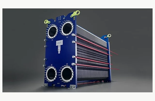
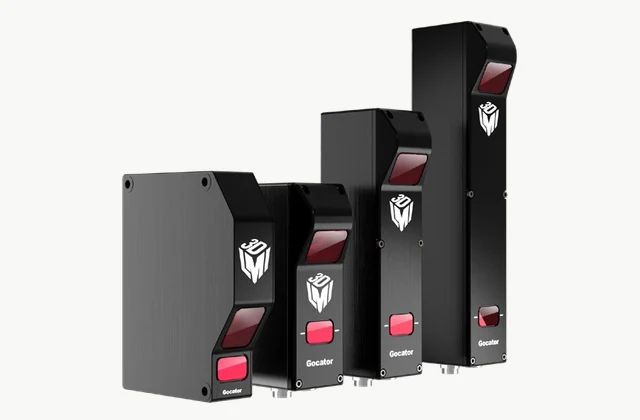
Related equipment references. The complete configuration is confirmed for your project.
Choose your application
The system library
Try a broader equipment or process term, or describe the application to our team.
Ask for an engineering review ↗02 / 198 system families
Define the evidence behind an accepted part.
Measure component features with complementary tactile and optical sensors.
Datum strategy, access and measurement uncertainty.
Measure surface topography and step features using optical interferometry.
Surface reflectivity, step height and vibration.
Measure distance or thickness using confocal chromatic sensing where optical interfaces permit.
Layer interface, optical access and calibration.
Evaluate roundness, cylindricity and related rotational form characteristics.
Part datum, rotary accuracy and probe strategy.
Measure defined gear-tooth geometry and report the required deviations.
Tooth geometry, datum and evaluation method.
Integrate helium leak detection with a suitable fixture or chamber test.
Leak-rate criterion, chamber method and background.
Verify selected electrical and functional conditions at the end of module assembly.
Test sequence, isolation and data traceability.
Test motor electrical condition and specified functional operating points at production release.
Load profile, electrical tests and thermal condition.
Measure gearbox noise and vibration under defined operating and loading conditions.
Load spectrum, background noise and order analysis.
Characterize valve flow and leakage at agreed test conditions.
Medium, pressure range and acceptance method.
Measure visible weld-bead profile during or after a joining operation.
Seam geometry, surface finish and line speed.
Assess the centering of optical elements relative to defined mechanical or optical references.
Optical axis, fixturing and centering tolerance.
Inspect internal features or defects through industrial X-ray computed tomography.
Part material, resolution and reconstruction needs.
Check connector pin assignment and specified electrical characteristics in a repeatable fixture.
Pin map, contact resistance and test coverage.
Grade printed or marked codes and verify their link to product identity.
Code quality, aggregation and data retention.
Apply a defined cyclic pressure duty to assess component endurance.
Pressure waveform, medium and cycle definition.
Measure cell impedance under controlled conditions and sort identified cells into agreed groups.
Test conditions, cell identification and sorting criteria.
Combine specified leak and electrical checks for a fuel-cell stack.
Gas boundary, test sequence and stack traceability.
Evaluate hydrogen-service components using a qualified pressure-test specification.
Test medium, pressure boundary and qualified test responsibility.
Present power semiconductor modules to an electrical test system under controlled conditions.
Device contact, thermal conditions and electrical test coverage.
Align optical interfaces while measuring the performance of a photonic module.
Optical interface, alignment objective and test repeatability.
Measure heat behavior of battery samples in an appropriately engineered test environment.
Sample condition, heat measurement and laboratory safeguards.
Inspect selected conformal-coating features on populated circuit boards.
Coating visibility, defect library and coverage evidence.
Measure hydraulic-pump performance at specified operating points.
Fluid condition, operating points and measurement uncertainty.
Evaluate leakage through valve external sealing boundaries using an approved emissions test method.
Test procedure, medium and evidence requirements.
Inspect composite pressure-vessel material using a selected nondestructive method.
Defect definition, material response and qualified evaluation.
Map internal acoustic indications in water-compatible components using automated ultrasonic scanning and position-linked C-scan records.
Acoustic access, reference defects and scan coverage.
Inspect conductive tube surfaces during production using eddy-current probes, encircling coils and position-linked defect records.
Tube geometry, material response and calibrated defect sensitivity.
Measure optically accessible layers and interfaces in transparent or partly transparent industrial materials using optical coherence tomography.
Optical penetration, layer interfaces and imaging repeatability.
Measure coating thickness and composition on suitable coated parts using X-ray fluorescence and a calibrated material model.
Coating stack, substrate composition and calibration references.
Measure surface vibration without a contact accelerometer and scan multiple positions to build a vibration response map.
Surface response, frequency range and measurement geometry.
Apply controlled mechanical vibration to mounted products for development or qualification against an agreed test profile.
Specimen mass, fixture dynamics and approved vibration profile.
Expose test articles to a defined combination of vacuum and thermal conditions for environmental verification.
Thermal boundary, vacuum performance and specimen instrumentation.
Test electric axle assemblies under controlled mechanical load while measuring electrical, torque, speed and thermal behavior.
Driveline interfaces, load map and thermal conditions.
Capture electroluminescence images of photovoltaic modules to evaluate electrically excited cell and interconnection patterns.
Module electrical interface, image quality and defect criteria.
Characterize solar-cell spectral response and external quantum efficiency using calibrated illumination and electrical measurement.
Spectral calibration, device geometry and measurement conditions.
Detect and map wafer surface indications for process monitoring using a defined optical inspection recipe.
Wafer surfaces, defect classes and inspection sensitivity.
Evaluate near-surface residual stress in suitable crystalline materials using X-ray diffraction and an application-specific analysis method.
Material phase, accessible geometry and stress evaluation method.
Generate and detect ultrasound optically for an agreed material inspection task.
Material attenuation, surface condition, geometry, target discontinuities, scan access and reference specimens.
Identify deformation patterns under controlled excitation in suitable bonded or composite structures.
Layup, bond geometry, surface finish, excitation method, inspection area and representative reference defects.
Evaluate suitable nonconductive coating layers using terahertz measurements.
Layer materials, expected thickness, curvature, substrate response, scan speed and reference cross-sections.
Image acoustic interfaces within suitable electronic packages and bonded components.
Package materials, acoustic penetration, target interfaces, coupling compatibility and reference delaminations.
Inspect suitable ferromagnetic parts for surface and near-surface indications.
Material, part geometry, defect orientations, handling sequence, demagnetization and inspection procedure.
Process suitable nonporous components through a controlled penetrant inspection sequence.
Surface finish, part geometry, material compatibility, cleaning sequence, dwell requirements and inspection conditions.
Screen accessible pipe sections using guided ultrasonic waves and position-related indications.
Pipe size, supports, coatings, contents, access points, attenuation and reference discontinuities.
Capture transient acoustic activity during an agreed structural loading or monitoring program.
Structure, loading history, sensor placement, propagation paths, noise sources and evaluation procedure.
Screen suitable ferromagnetic tank floors for material-loss indications.
Plate thickness, coatings, corrosion morphology, floor access, weld zones and reference defects.
Capture digital radiographs for a qualified weld or casting inspection procedure.
Material thickness, weld geometry, detector access, image-quality references, positioning and qualified radiation provisions.
Observe thermal response to synchronized excitation for suitable material or bond inspection.
Material stack, thickness, surface emissivity, excitation method, reference defects and camera geometry.
Track conductivity-related distributions inside a process vessel using an engineered electrode arrangement.
Vessel geometry, phase conductivities, electrode compatibility, mixing dynamics and reconstruction requirements.
Image suitable specimens at high magnification using an electron-beam microscopy workflow.
Materials, conductive treatment, feature size, analytical options, specimen dimensions and laboratory utilities.
Combine localized ion-beam preparation and electron imaging for material cross-section investigation.
Target features, material stack, cross-section objective, sample mounting and contamination constraints.
Analyze electron-transparent specimens through transmission imaging and selected analytical modes.
Material, thickness preparation, desired structural information, holder needs and laboratory stability.
Map crystallographic orientation and related microstructural information in prepared specimens.
Material phases, grain dimensions, specimen preparation, microscope interface and mapping objective.
Investigate surface elemental and chemical-state information with X-ray photoelectron spectroscopy.
Material, target chemical states, surface handling, charging behavior, analysis area and depth-profile needs.
Investigate surface species and spatial distributions using secondary-ion mass analysis.
Material stack, target species, lateral and depth objectives, reference materials and sample-handling constraints.
Measure suitable surface topography and selected local properties through a scanning probe.
Surface roughness, feature scale, sample dimensions, mechanical stability and required measurement modes.
Map Raman spectral information across suitable samples for chemical or structural investigation.
Material composition, target phases, spatial scale, optical access and reference spectra.
Acquire infrared spectra from suitable samples using an agreed sampling accessory.
Sample form, spectral features, transmission or reflection accessory, reference library and preparation workflow.
Monitor a suitable process stream using near-infrared spectra and a validated calibration model.
Feed variability, target property, sampling interface, calibration samples and reference analytical method.
Analyze suitable samples through a defined benchtop magnetic-resonance measurement method.
Sample chemistry, solvent or matrix, target analytes, temperature needs and intended quantitative method.
Investigate suitable paramagnetic species with electron paramagnetic resonance spectroscopy.
Sample matrix, target species, expected signal, temperature range and measurement accessories.
Evaluate suitable material elemental signatures using laser-induced emission spectra.
Material classes, target elements, surface condition, reference standards and sampling geometry.
Measure selected elements in suitable conductive metal specimens using spark emission spectroscopy.
Alloy families, target elements, concentration ranges, sample geometry and calibration standards.
Analyze prepared liquid samples for selected elements using plasma optical emission.
Analytes, sample matrix, digestion requirements, detection objectives, interferences and laboratory utilities.
Measure selected elemental species in prepared samples using plasma mass spectrometry.
Target elements, sample matrix, contamination control, interference strategy and analytical reporting limits.
Separate and identify suitable volatile compounds through a defined GC-MS workflow.
Analytes, sample matrix, preparation, column strategy, reference standards and identification requirements.
Separate suitable compounds in liquid samples and analyze them by mass spectrometry.
Target compounds, matrix, extraction method, chromatography, standards and reporting objectives.
Separate and quantify selected ionic species in prepared liquid samples.
Target ions, sample concentration, matrix load, preparation, calibration and analytical limits.
Measure heat-flow differences associated with thermal transitions in suitable samples.
Material, expected transitions, sample preparation, atmosphere and reference method.
Measure sample mass change during a defined thermal and atmosphere program.
Sample composition, temperature program, atmosphere, pan compatibility and expected mass-change range.
Characterize sample mechanical response under controlled oscillatory loading and temperature.
Material form, fixture mode, strain range, temperature program and expected transition behavior.
Measure dimensional change of suitable specimens during a defined temperature cycle.
Sample geometry, material expansion, temperature range, atmosphere and contact-load constraints.
Determine thermal response of suitable specimens following a controlled energy pulse.
Material, thickness, coatings, temperature range, density and heat-capacity data requirements.
Measure steady-state heat transfer through suitable insulation or solid specimens.
Specimen dimensions, thermal resistance, contact conditions, mean temperature and environmental requirements.
Measure flow and deformation behavior of suitable fluids or soft materials under defined shear.
Material consistency, shear range, geometry, temperature control and expected slip or evaporation.
Characterize pressure-driven flow of suitable melts or viscous materials through a defined die.
Material, temperature range, die geometry, pressure limits and correction method.
Evaluate bulk powder shear behavior to support handling and storage design.
Particle distribution, moisture, consolidation stress, wall materials and handling objective.
Characterize suitable material surface area and pore behavior using gas adsorption.
Sample stability, expected area, pore range, conditioning limits and adsorptive gas.
Evaluate through-pore characteristics of suitable membranes or porous media.
Material wetting, pore range, sample thickness, support fixture and test fluid compatibility.
Measure skeletal volume and derived density of suitable solid or powder samples.
Sample mass, material porosity, gas compatibility, conditioning and temperature stability.
Determine an equivalent particle-size distribution from an agreed laser-scattering method.
Particle material, size range, dispersion route, refractive data and sample stability.
Characterize suitable dispersions through light-scattering size and electrophoretic measurements.
Dispersant, concentration, conductivity, viscosity, temperature and particle stability.
Measure particle images to evaluate agreed size and shape descriptors.
Particle contrast, size range, dispersion, shape descriptors and sample throughput.
Evaluate wetting and interfacial behavior using controlled drop or surface measurements.
Substrate cleanliness, test liquids, drop method, temperature and analysis objective.
Measure mass response of suitable materials exposed to controlled vapor conditions.
Sample stability, vapor identity, humidity or pressure program, equilibrium criteria and temperature.
Evaluate local mechanical response of suitable materials and coatings through controlled indentation.
Material, coating thickness, roughness, indentation scale, substrate effects and target properties.
Apply controlled cyclic loads to suitable specimens or components for an agreed fatigue program.
Specimen geometry, load spectrum, frequency, environment, gripping and failure definition.
Measure time-dependent deformation under sustained load and controlled temperature.
Material, specimen, load and temperature program, extensometry and duration requirements.
Evaluate crack-resistance behavior using qualified specimen geometry and loading procedures.
Material, specimen thickness, notch preparation, crack method, environment and evaluation procedure.
Compare material pairs under an agreed sliding or rolling contact test.
Material pairs, contact geometry, load, motion, lubrication, temperature and wear measurement.
Measure switching behavior of suitable power devices within an engineered pulsed test fixture.
Device package, electrical envelope, gate interface, probe bandwidth and measurement boundary.
Present controlled radar-return scenarios for automotive sensor and system testing.
Radar bands, target distance and velocity scenarios, channel count, chamber interface and timing.
Provide a controlled electromagnetic test environment for an agreed emissions or immunity program.
Equipment dimensions, test methods, frequency coverage, antenna distance, utilities and access requirements.
Measure antenna or wireless-device radiation behavior in a controlled spatial test setup.
Device bands, antenna geometry, positioner, chamber environment, polarization and measurement objectives.
Measure carbon-related water quality using an agreed analytical oxidation and detection method.
Water matrix, carbon range, particulates, salts, sampling frequency and reporting objective.
Measure selected bulk elemental contents in prepared solid or liquid samples.
Sample composition, target elements, sample mass, reference materials and preparation workflow.
Monitor suitable volatile compounds through a defined direct mass-spectrometry sampling method.
Target VOCs, sample humidity, matrix composition, inlet response and calibration strategy.
Quantify lens contrast transfer across field positions.
Focal length, aperture, conjugates, field angles and spectral band.
Characterize assembled camera response rather than an isolated lens.
Sensor interface, chart distance, illumination, exposure and image format.
Evaluate near-eye optical imaging through a defined eyebox.
Eye relief, pupil positions, virtual distance, field and display interface.
Determine optical glass dispersion using angular measurements.
Prism geometry, wavelengths, temperature, sample mounting and index range.
Measure small angular deviations using an optical return path.
Mirror aperture, working distance, angular range, mounting and vibration.
Collect optical flux for a defined source and detector combination.
Source size, spectrum, ports, detector response and thermal stabilization.
Measure prism geometry independently of optical imaging performance.
Prism faces, aperture, fixture access, angle range and surface quality.
Reconstruct optical wavefront slopes through a lenslet sensor.
Beam diameter, wavelength, dynamic range, sampling and reference wavefront.
Measure lens thickness and assembly air gaps optically.
Material index, surface curvature, coating, thickness range and fixture.
Inspect cosmetic surface defects using defined optical illumination.
Surface geometry, defect classification, aperture, lighting and reference artifacts.
Measure complex scattering parameters of RF devices.
Frequency band, ports, power levels, fixtures and calibration planes.
Resolve signal frequency content and unwanted emissions.
Frequency span, bandwidth, dynamic range, modulation and input protection.
Characterize oscillator spectral purity near its carrier.
Carrier frequency, offset range, source level, reference and stability.
Measure added noise in receivers and amplifiers.
Frequency band, gain, impedance, noise source and fixture loss.
Characterize amplifier behavior across controlled impedance states.
Device bias, frequency, power, tuners, harmonic control and cooling.
Connect on-wafer RF structures to calibrated microwave instruments.
Pad geometry, frequency extenders, probe pitch, chuck and thermal conditions.
Evaluate digital link errors under controlled stimulus and stress.
Line rate, coding, channels, jitter, equalization and test duration.
Compare RF power sensors with a traceable reference chain.
Frequency, power range, connectors, transfer standards and mismatch.
Measure permittivity and loss using a chosen microwave fixture.
Material form, frequency band, thickness, anisotropy and temperature.
Supply controlled modulated signals for receiver development.
Carrier band, waveform, bandwidth, synchronization and output power.
Resolve carrier transport properties in prepared material samples.
Sample geometry, contacts, magnetic field, temperature and current.
Measure magnetic moment as a function of controlled field.
Sample moment, holder background, field range and temperature.
Characterize surface magnetization through polarized optical response.
Film geometry, wavelength, field orientation, spot and temperature.
Measure polarization response under controlled electric excitation.
Film thickness, electrodes, drive waveform, leakage and temperature.
Resolve dielectric response over frequency and temperature.
Electrode geometry, sample dimensions, frequency span, voltage and environment.
Measure optical emission decay following pulsed excitation.
Excitation wavelength, pulse response, emission band and sample geometry.
Map recombination-related response over prepared semiconductor samples.
Material, injection level, surface preparation, scan area and calibration.
Assess light-induced surface potential response in semiconductors.
Illumination band, contacts, sample treatment, atmosphere and modulation.
Measure electrical transport and Seebeck response under thermal gradients.
Sample shape, contacts, atmosphere, temperature and gradient range.
Map contact potential differences without asserting absolute composition.
Surface condition, probe geometry, humidity, scan spacing and reference.
Apply independent in-plane loads to cruciform specimens.
Specimen arms, force ratio, strain field, grips and control sequence.
Measure material response at specified rapid deformation rates.
Specimen shape, loading speed, force bandwidth, temperature and imaging.
Measure absorbed energy and force history during pendulum impact.
Specimen notch, support geometry, striker, temperature and energy range.
Apply controlled falling-mass impact to specimens or components.
Mass, impact velocity, nose geometry, fixture and sensor bandwidth.
Cycle components under controlled torque and angular displacement.
Torque spectrum, specimen geometry, fixtures, frequency and environment.
Coordinate temperature cycles and mechanical strain histories.
Alloy, gauge length, heating method, phase relation and cooling.
Measure displacement and strain fields from correlated images.
Field of view, speckle, stereo geometry, frame rate and lighting.
Map indentation hardness over prepared cross-sections.
Material, load, indentation spacing, polishing and optical contrast.
Evaluate limited-volume specimens using a defined punch geometry.
Disc thickness, punch size, support, displacement and temperature.
Estimate near-surface residual stresses using relieved strains.
Material elasticity, rosette geometry, drilling increments and surface preparation.
Compare a flow meter against collected liquid mass over time.
Liquid properties, flow span, collection timing, weighing and temperature.
Establish gas volume flow from controlled bell displacement.
Gas, bell geometry, pressure, temperature, displacement and leakage.
Establish flow from swept volume and measured displacement time.
Fluid, piston dimensions, seal leakage, pressure and temperature.
Infer gas flow from pressure volume temperature and time.
Gas composition, collection volume, thermal equilibrium and timing.
Use calibrated sonic nozzles as gas-flow transfer standards.
Gas properties, upstream state, nozzle set and pressure ratio.
Provide characterized airflow for velocity instrument calibration.
Speed range, test section, blockage, probe orientation and turbulence.
Characterize pressure sensor response to time-varying pressure inputs.
Waveform, pressure span, frequency, medium and reference bandwidth.
Generate pressure from controlled force on a piston area.
Medium, pressure range, piston assembly, masses and temperature.
Realize defined material transition temperatures for thermometer calibration.
Fixed-point cells, immersion depth, thermometer geometry and thermal cycling.
Produce controlled moist gas for hygrometer comparison.
Dew point range, pressure, flow, chamber and contamination constraints.
Count aerosol particles after controlled condensational growth.
Aerosol concentration, size response, working fluid, inlet and flow.
Resolve aerosol size distribution through electrical mobility classification.
Particle charge, mobility range, neutralizer, flows and scan sequence.
Determine particle aerodynamic response using timed acceleration measurements.
Aerosol density assumptions, size band, inlet and concentration.
Resolve aerosol stages using inertial separation and electrical detection.
Pressure stages, aerosol loading, charging and sampling conditions.
Estimate aerosol loading from calibrated light scattering.
Aerosol optical properties, concentration, size and sampling path.
Measure filter penetration across a controlled particle challenge.
Filter size, face velocity, aerosol spectrum, loading and leakage.
Track particle counts at defined critical sampling locations.
Sampling points, tubing losses, size channels, alarms and operating states.
Prepare particle samples for instruments without uncontrolled overload.
Concentration, dilution ratio, temperature, humidity and particle volatility.
Resolve flow velocity fields using seeded optical imaging.
Flow geometry, seeding, laser sheet, frame timing and optical access.
Measure droplet velocity and size from optical phase signals.
Spray medium, droplet range, access angles, obscuration and traverse.
Assess self-heating behavior under a defined low-heat-loss protocol.
Sample composition, mass, vessel, pressure, detection threshold and venting.
Measure reaction heat during a controlled synthesis sequence.
Recipe, dosing rates, mixing, temperature, heat transfer and sampling.
Measure small sustained heat flows at controlled temperature.
Sample form, background, equilibration, atmosphere and detection timescale.
Measure combustion energy in a sealed oxygen environment.
Sample preparation, moisture, ignition aid, oxygen and vessel capacity.
Identify gases released during a programmed thermal experiment.
Heating program, transfer line, gas species, detector and sample mass.
Measure mass changes under controlled vapor or reactive gas exposure.
Gas composition, buoyancy, temperature, pressure and sample geometry.
Automate endpoint determination for a defined chemical assay.
Analyte, titrant, electrode, solvent, dosing increments and sample preparation.
Quantify water using a specified Karl Fischer method.
Matrix, water level, extraction, reagent compatibility and interference.
Determine a liquid flash point using a selected test geometry.
Method, sample volatility, heating rate, ignition source and temperature.
Characterize boiling behavior using a specified distillation procedure.
Sample composition, pressure correction, heating profile and receiver cooling.
Measure device electrical parameters through defined wafer test structures.
Pad map, probe contacts, voltage, current range and environment.
Characterize static device conduction and blocking behavior.
Device class, voltage, current, pulse width, fixtures and cooling.
Measure transient current-voltage response with controlled pulse timing.
Pulse width, duty cycle, bias, parasitics and synchronization.
Measure junction or gate capacitance versus bias.
Frequency, AC amplitude, bias, leakage and contact geometry.
Apply electrical and thermal stress to selected wafer structures.
Stress profile, monitoring channels, temperature, pad map and failure criteria.
Characterize transient thermal response using electrical temperature indicators.
Device mounting, heating power, sensing parameter and cooling boundary.
Screen packaged devices using agreed thermal and electrical stressing.
Device interfaces, stress voltages, temperature, load boards and monitoring.
Evaluate a defined module insulation test sequence.
Isolation paths, voltage waveform, discharge detection and environmental state.
Measure light-current-voltage behavior of light-emitting devices.
Wavelength band, current drive, optical collection, temperature and contacts.
Evaluate probe contact geometry and electrical paths before wafer use.
Probe layout, overtravel, contact force, resistance and planarity.
Expose specimens to controlled rapid temperature transitions.
Specimen mass, temperature extremes, transfer time and cycle count.
Combine low pressure with controlled temperature and humidity exposure.
Pressure profile, moisture constraints, specimen heat load and feedthroughs.
Apply combined thermal and vibration stresses for design exploration.
Specimen fixtures, vibration axes, ramp sequence and monitored functions.
Cycle corrosive spray moisture and drying conditions.
Exposure recipe, solution, specimen loading, airflow and collection rate.
Expose products to controlled radiation and thermal conditions.
Spectrum, irradiance, sample plane, temperature and exposure program.
Apply controlled water exposure using selected nozzle or rain geometry.
Enclosure size, nozzle type, flow, pressure, distance and motion.
Expose enclosures to controlled particulate circulation and pressure conditions.
Dust type, concentration, enclosure volume, pressure and exposure duration.
Evaluate material response under specified humid SO2 exposure.
Gas dose, chamber volume, humidity, specimen layout and cycle sequence.
Expose strained elastomer specimens to a controlled ozone atmosphere.
Ozone level, strain, temperature, humidity and specimen formulation.
Coordinate vibration loading with temperature or humidity exposure.
Specimen mass, fixture, vibration spectrum, chamber profile and access.
Measure airflow through a defined textile area and pressure difference.
Fabric type, test area, pressure differential, conditioning and clamping.
Determine liquid penetration response under controlled pressure.
Fabric finish, pressure ramp, exposure side, area and endpoint.
Apply multidirectional abrasion using defined textiles and loading.
Abradant, load, specimen backing, cycle count and grading procedure.
Characterize liquid spreading and transport through fabrics.
Test liquid, specimen conditioning, dosing, contact and measurement channels.
Evaluate insulation of an assembled clothing ensemble on a controlled heated form.
Garment fit, body segments, air movement, posture, heating and ambient conditions.
Evaluate textile water-vapor resistance with a controlled sweating surface.
Membrane, water supply, airflow, humidity and specimen contact.
Quantify fabric deformation over a defined support geometry.
Specimen diameter, support, conditioning, orientation and image capture.
Load a clamped fabric through a controlled expanding diaphragm.
Specimen area, pressure rate, diaphragm correction and material conditioning.
Measure hydraulic behavior of a geotextile under a defined boundary.
Normal load, hydraulic head, specimen direction, saturation and water quality.
Measure heat release under controlled radiant exposure.
Specimen dimensions, heat flux, exhaust flow, ignition and conditioning.
From application to equipment scope
Share the product or feed, required output, site and destination. IndustryApex reviews the equipment, interfaces and OEM / ODM scope with you.
Selection resources define possible process scopes. Technical feasibility, the offered configuration, supply, installation and support are confirmed for each project. Photographs identify related reference equipment, not completed IndustryApex installations.
Compare selection boundaries, integration requirements, complete cost scope and acceptance records across advanced industrial systems.
Explore system selection guides ↗