
Select a pneumatic directional valve from the cylinder circuit, port function, pressure range and required flow. Confirm coil supply, pilot requirements and the de-energized state, then prove actuator behavior with the actual tubing and controls. Run the intended actuator sequence through minimum-pressure and simultaneous-demand conditions. Check travel times, pressure drop, leaks and the documented de-energized behavior. Verify wiring against the actual coil variant and record valve, tubing and muffler details so later substitution remains controlled. Submit the intended configuration and any OEM/ODM changes for project-specific feasibility review.
Select a pneumatic directional valve from the cylinder circuit, port function, pressure range and required flow. Confirm coil supply, pilot requirements and the de-energized state, then prove actuator behavior with the actual tubing and controls.
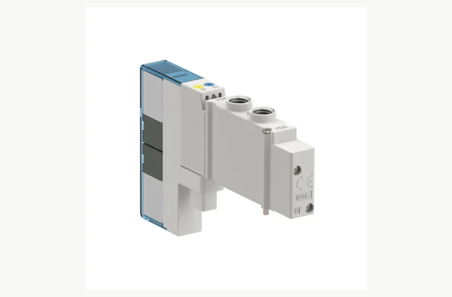
Shown as a configuration reference. Availability and the equipment offered for your project are confirmed separately.
Define port and position function
State the circuit function, number of ports and positions and the required center condition where applicable. A valve with similar external dimensions can connect pressure and exhaust differently. Supply the pneumatic diagram so proposals are compared by symbol and behavior rather than appearance.
Size flow for the actuator cycle
Provide actuator bore, stroke, load and desired travel time with tubing length and fittings. Pressure drop and exhaust restrictions affect speed. A large port thread does not necessarily mean adequate internal flow, and the valve must be reviewed as part of the complete pneumatic circuit.
Check pilot and operating pressure
Confirm minimum and maximum pressure and whether the valve is internally or externally piloted. Low-pressure or vacuum duty can need a different arrangement. The selection must also consider supply variation during simultaneous movements, not just static pressure before the machine starts.
Specify electrical commands and connectors
Match coil voltage, control output, suppression and connector type with the cabinet design. Check any polarity requirements and diagnostic signals. A mechanically compatible replacement can behave differently electrically, so the ordered part code and wiring documentation must identify the complete variant.
Review the loss-of-power state
A single-solenoid spring return and a double-solenoid memory arrangement have different behavior. Determine the resulting cylinder movement or pressure retention when power is lost. Standard directional valves must not be represented as validated safety functions without an engineered system assessment and appropriate evidence.
Plan exhaust and contamination service
Specify filtration, lubrication rules, mufflers and permitted operating environment. Exhaust blockage can change cycle time and residual pressure. Obtain replacement coil, seal and valve identification, and retain access to manual overrides only within the machine's approved commissioning and maintenance procedure.
Compare a complete pneumatic directional valve scope
| Decision | Information to compare |
|---|---|
| Define port and position function | Pneumatic symbol, port/position count and center condition |
| Size flow for the actuator cycle | Actuator demand, flow requirement, tubing and allowable pressure drop |
| Check pilot and operating pressure | Working pressure range, pilot method, supply variation and vacuum use |
| Specify electrical commands and connectors | Coil voltage, output type, suppression, polarity and connector pinout |
| Review the loss-of-power state | De-energized spool state, retained pressure and approved stop strategy |
| Plan exhaust and contamination service | Air quality, exhaust/mufflers, manual override rules and service parts |
Plan installation and access
Connect the valve using the approved port map and thread practice, with tubing supported and exhaust paths kept clear. Confirm grounding and electrical protection. Isolate stored air before service and prevent initial coil tests from causing unexpected movement of a connected actuator.
Agree acceptance evidence before ordering
Run the intended actuator sequence through minimum-pressure and simultaneous-demand conditions. Check travel times, pressure drop, leaks and the documented de-energized behavior. Verify wiring against the actual coil variant and record valve, tubing and muffler details so later substitution remains controlled.
Define OEM/ODM engineering boundaries
OEM connectors, mounting and approved coil/port variants may be reviewed. ODM spool, seal, flow or safety-related changes need engineering and endurance testing. A reference valve image does not establish safe-system validation or permission to transfer another manufacturer's specifications to an alternative.
Prepare comparable quotations
Use the pneumatic directional valve inquiry to identify the duty described above, the included configuration and the evidence that will demonstrate it. Separate base equipment from required accessories, commissioning and operator training. Record deviations against the requested pneumatic symbol, port/position count and center condition before price comparison. The illustrated reference establishes a discussion point; the offered unit still needs its own identifiable configuration and written commercial scope.
What should your pneumatic directional valve RFQ include?
- Pneumatic symbol, port/position count and center condition
- Actuator demand, flow requirement, tubing and allowable pressure drop
- Working pressure range, pilot method, supply variation and vacuum use
- Coil voltage, output type, suppression, polarity and connector pinout
- De-energized spool state, retained pressure and approved stop strategy
- Air quality, exhaust/mufflers, manual override rules and service parts
- Destination, working environment, access and delivery constraints
- Installation responsibility, utilities and connection drawings
- Acceptance samples, documented test method, operator training and maintenance scope
- OEM/ODM changes requested: identification, tooling, interfaces or new design; engineering feasibility to be confirmed
Need OEM / ODM customization?
Submit branding, packaging, configuration or engineering requirements for this equipment. Include the target market, initial and annual quantities, required changes and acceptance criteria.
Customization feasibility, permitted branding, development responsibilities, minimum quantity, cost and lead time are reviewed for the proposed supplier and configuration before a quotation is confirmed.
Frequently asked questions
How do I define port and position function?
State the circuit function, number of ports and positions and the required center condition where applicable. A valve with similar external dimensions can connect pressure and exhaust differently. Supply the pneumatic diagram so proposals are compared by symbol and behavior rather than appearance.
How do I size flow for the actuator cycle?
Provide actuator bore, stroke, load and desired travel time with tubing length and fittings. Pressure drop and exhaust restrictions affect speed. A large port thread does not necessarily mean adequate internal flow, and the valve must be reviewed as part of the complete pneumatic circuit.
How do I check pilot and operating pressure?
Confirm minimum and maximum pressure and whether the valve is internally or externally piloted. Low-pressure or vacuum duty can need a different arrangement. The selection must also consider supply variation during simultaneous movements, not just static pressure before the machine starts.
How do I specify electrical commands and connectors?
Match coil voltage, control output, suppression and connector type with the cabinet design. Check any polarity requirements and diagnostic signals. A mechanically compatible replacement can behave differently electrically, so the ordered part code and wiring documentation must identify the complete variant.
How do I review the loss-of-power state?
A single-solenoid spring return and a double-solenoid memory arrangement have different behavior. Determine the resulting cylinder movement or pressure retention when power is lost. Standard directional valves must not be represented as validated safety functions without an engineered system assessment and appropriate evidence.
How do I plan exhaust and contamination service?
Specify filtration, lubrication rules, mufflers and permitted operating environment. Exhaust blockage can change cycle time and residual pressure. Obtain replacement coil, seal and valve identification, and retain access to manual overrides only within the machine's approved commissioning and maintenance procedure.
Reference information
- SMC JSY3000 official product reference
- SMC pneumatic directional valve official family or technical reference
Reference data and images explain equipment configurations. IndustryApex engineers confirm the offered model, specification and commercial scope in your project quotation.