
Choose a pneumatic cylinder by required force at available pressure, stroke, mounting and the full machine cycle. Assess rod loading, cushioning and position sensing with the real air circuit. Bore diameter alone does not establish usable force, speed or guidance. Cycle the real load at minimum and normal available pressure, checking force, stroke time, leakage and end impacts. Verify switch signals against physical positions and test the approved stop and restart sequence. Record tubing, valves, flow settings and mounting because changes to them alter cylinder behavior. Submit the intended configuration and any OEM/ODM changes for project-specific feasibility review.
Choose a pneumatic cylinder by required force at available pressure, stroke, mounting and the full machine cycle. Assess rod loading, cushioning and position sensing with the real air circuit. Bore diameter alone does not establish usable force, speed or guidance.
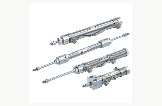
Shown as a configuration reference. Availability and the equipment offered for your project are confirmed separately.
Define push and pull force separately
Provide the load direction and required force throughout the stroke. Rod-side effective area differs from the full piston area, while friction and supply losses affect output. Use point-of-use pressure under flow in the sizing review rather than assuming the compressor's headline pressure reaches the cylinder.
Match stroke and mounting geometry
Specify stroke, pivot or fixed mounting, installation envelope and the driven mechanism. Check alignment through travel and any change in linkage angle. A correctly sized bore can still fail if the selected mounting introduces bending, binding or an unsuitable rod-end connection.
Provide independent load guidance
An ordinary piston rod should not be treated as a bearing for a heavy overhung tool. Review side loads, moments and buckling with the supplier. Add external guides or select a guided arrangement where the mechanism demands them, keeping guidance and cylinder thrust as separate engineering duties.
Review speed and cushioning together
Cylinder speed depends on valve flow, tubing, exhaust restrictions and the moving mass. Define the required cycle and inspect end impacts. Cushioning or an external absorber must fit the actual energy; simply opening a speed controller further can increase shock and reduce reliable stopping behavior.
Specify sensing and pressure-loss behavior
Confirm switch type, location, electrical interface and what constitutes an accepted end position. Review the response to lost pressure or power in the complete machine. A double-acting cylinder does not inherently hold a vertical load safely when its supply is isolated.
Choose seals and maintainable air quality
State temperature, dust, cleaning chemicals and any special air requirements. Verify permitted lubrication and seal materials for the offered variant. Obtain the exact seal and mounting part identifiers and keep access for inspection without dismantling the driven machine unnecessarily.
Compare a complete pneumatic cylinder scope
| Decision | Information to compare |
|---|---|
| Define push and pull force separately | Push/pull loads, point-of-use pressure and force margin |
| Match stroke and mounting geometry | Stroke, mounting style, rod-end interface and linkage geometry |
| Provide independent load guidance | Side load, overhang, rod buckling, orientation and external guides |
| Review speed and cushioning together | Moving mass, speed, valve/tube circuit and end cushioning |
| Specify sensing and pressure-loss behavior | Position switches, machine interlocks, pressure-loss state and load retention |
| Choose seals and maintainable air quality | Environment, seal compatibility, air quality, lubrication and service parts |
Plan installation and access
Align cylinder and driven guide before pressurizing, using the specified fasteners and rod-end arrangement. Fit air controls and exhaust provisions to the engineered circuit. Provide safe isolation of stored pneumatic energy and protect pinch points during adjustment and initial movement.
Agree acceptance evidence before ordering
Cycle the real load at minimum and normal available pressure, checking force, stroke time, leakage and end impacts. Verify switch signals against physical positions and test the approved stop and restart sequence. Record tubing, valves, flow settings and mounting because changes to them alter cylinder behavior.
Define OEM/ODM engineering boundaries
OEM mounting, rod-end, sensor and permitted stroke options can be reviewed. ODM bore, rod, seals or retention features require mechanical and endurance evidence. A manufacturer's reference image is not proof of stock, authorized agency or validated performance of a customized cylinder.
What should your pneumatic cylinder RFQ include?
- Push/pull loads, point-of-use pressure and force margin
- Stroke, mounting style, rod-end interface and linkage geometry
- Side load, overhang, rod buckling, orientation and external guides
- Moving mass, speed, valve/tube circuit and end cushioning
- Position switches, machine interlocks, pressure-loss state and load retention
- Environment, seal compatibility, air quality, lubrication and service parts
- Destination, working environment, access and delivery constraints
- Installation responsibility, utilities and connection drawings
- Acceptance samples, documented test method, operator training and maintenance scope
- OEM/ODM changes requested: identification, tooling, interfaces or new design; engineering feasibility to be confirmed
Need OEM / ODM customization?
Submit branding, packaging, configuration or engineering requirements for this equipment. Include the target market, initial and annual quantities, required changes and acceptance criteria.
Customization feasibility, permitted branding, development responsibilities, minimum quantity, cost and lead time are reviewed for the proposed supplier and configuration before a quotation is confirmed.
Frequently asked questions
How do I define push and pull force separately?
Provide the load direction and required force throughout the stroke. Rod-side effective area differs from the full piston area, while friction and supply losses affect output. Use point-of-use pressure under flow in the sizing review rather than assuming the compressor's headline pressure reaches the cylinder.
How do I match stroke and mounting geometry?
Specify stroke, pivot or fixed mounting, installation envelope and the driven mechanism. Check alignment through travel and any change in linkage angle. A correctly sized bore can still fail if the selected mounting introduces bending, binding or an unsuitable rod-end connection.
How do I provide independent load guidance?
An ordinary piston rod should not be treated as a bearing for a heavy overhung tool. Review side loads, moments and buckling with the supplier. Add external guides or select a guided arrangement where the mechanism demands them, keeping guidance and cylinder thrust as separate engineering duties.
How do I review speed and cushioning together?
Cylinder speed depends on valve flow, tubing, exhaust restrictions and the moving mass. Define the required cycle and inspect end impacts. Cushioning or an external absorber must fit the actual energy; simply opening a speed controller further can increase shock and reduce reliable stopping behavior.
How do I specify sensing and pressure-loss behavior?
Confirm switch type, location, electrical interface and what constitutes an accepted end position. Review the response to lost pressure or power in the complete machine. A double-acting cylinder does not inherently hold a vertical load safely when its supply is isolated.
How do I choose seals and maintainable air quality?
State temperature, dust, cleaning chemicals and any special air requirements. Verify permitted lubrication and seal materials for the offered variant. Obtain the exact seal and mounting part identifiers and keep access for inspection without dismantling the driven machine unnecessarily.
Reference information
- SMC CJ2 official product reference
- SMC pneumatic cylinder official family or technical reference
Reference data and images explain equipment configurations. IndustryApex engineers confirm the offered model, specification and commercial scope in your project quotation.