
Choose a guided pneumatic slide for the load moments, required travel and repeatability of the assembly operation. Evaluate the integrated guide, stroke stops and end-of-stroke energy with the valve and air circuit, rather than selecting by bore alone. Cycle representative loads through the real valve circuit at the available point-of-use pressure. Measure tool-point repeatability, vibration and time to confirmed position. Include cold restart, adjusted stroke and a simulated missing-position signal, retaining stop, flow-control and sensor settings with the approved tooling revision. Submit the intended configuration and any OEM/ODM changes for project-specific feasibility review.
Choose a guided pneumatic slide for the load moments, required travel and repeatability of the assembly operation. Evaluate the integrated guide, stroke stops and end-of-stroke energy with the valve and air circuit, rather than selecting by bore alone.
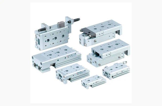
Shown as a configuration reference. Availability and the equipment offered for your project are confirmed separately.
Identify loads on the moving table
Supply payload, center of gravity, tooling overhang and forces applied during the operation. Integrated guides carry moments that an ordinary cylinder rod should not be asked to resist. Check the full load case with the manufacturer's selection method, including acceleration and off-axis process reactions.
Match stroke and working envelope
State usable travel, approach clearance and the minimum space around tooling at both endpoints. Include sensor and adjustment access. A compact body can still require additional room for the moving load, fittings and speed controllers, especially when mounted beside other assembly stations.
Assess guide stiffness and repeatability
Define repeatability at the actual tool or part location and in the relevant load direction. Clearance, mounting flatness and workholding affect the result. An actuator body's catalog repeatability cannot by itself establish the accuracy of a long, flexible tool attached to its moving table.
Control speed and end-stop energy
Air pressure, valve flow and load inertia determine how the slide reaches its stops. Review adjustment bolts, cushioning and shock absorbers in the offered variant. Raising air pressure to recover cycle time may increase impact without solving an undersized valve or unsuitable stop-energy condition.
Define sensors and sequence signals
Specify the end-position switches, mounting grooves and electrical interfaces used by the machine. Include checks for a slide that fails to reach position. A switch signal should be evaluated against the real stopping point and required sequence, especially when adjustable stops change the endpoint.
Maintain clean air and guide service
Confirm the air quality and lubrication requirements of the selected slide. Protect exposed guides from chips or adhesive debris and provide access for inspection. Obtain the correct guide, seal and stop components, since replacing one of these can require rechecking tool position and impact settings.
Compare a complete guided pneumatic slide scope
| Decision | Information to compare |
|---|---|
| Identify loads on the moving table | Payload, center of gravity, overhang, moments and process forces |
| Match stroke and working envelope | Stroke, approach clearance, moving-tool envelope and fitting access |
| Assess guide stiffness and repeatability | Tool-point repeatability, deflection limits, guide loading and mounting flatness |
| Control speed and end-stop energy | Travel speed, valve flow, cushioning, stop adjustment and impact energy |
| Define sensors and sequence signals | Position switches, electrical interface, timeout and adjusted-stop confirmation |
| Maintain clean air and guide service | Air quality, contamination protection, guide/seal parts and reset procedure |
Plan installation and access
Mount the slide on a sufficiently flat and rigid surface using the specified locating and fastening method. Avoid tightening it into a distorted frame. Route air tubing and sensor cables clear of travel, support the tooling and review pinch points before introducing pressure.
Agree acceptance evidence before ordering
Cycle representative loads through the real valve circuit at the available point-of-use pressure. Measure tool-point repeatability, vibration and time to confirmed position. Include cold restart, adjusted stroke and a simulated missing-position signal, retaining stop, flow-control and sensor settings with the approved tooling revision.
Define OEM/ODM engineering boundaries
OEM mounting plates, tooling and sensor interfaces can be reviewed. ODM guide, piston or stop changes need mechanical calculations and endurance testing. The reference slide image establishes a product family and does not transfer manufacturer approval or catalog performance to a modified alternative.
What should your guided pneumatic slide RFQ include?
- Payload, center of gravity, overhang, moments and process forces
- Stroke, approach clearance, moving-tool envelope and fitting access
- Tool-point repeatability, deflection limits, guide loading and mounting flatness
- Travel speed, valve flow, cushioning, stop adjustment and impact energy
- Position switches, electrical interface, timeout and adjusted-stop confirmation
- Air quality, contamination protection, guide/seal parts and reset procedure
- Destination, working environment, access and delivery constraints
- Installation responsibility, utilities and connection drawings
- Acceptance samples, documented test method, operator training and maintenance scope
- OEM/ODM changes requested: identification, tooling, interfaces or new design; engineering feasibility to be confirmed
Need OEM / ODM customization?
Submit branding, packaging, configuration or engineering requirements for this equipment. Include the target market, initial and annual quantities, required changes and acceptance criteria.
Customization feasibility, permitted branding, development responsibilities, minimum quantity, cost and lead time are reviewed for the proposed supplier and configuration before a quotation is confirmed.
Frequently asked questions
How do I identify loads on the moving table?
Supply payload, center of gravity, tooling overhang and forces applied during the operation. Integrated guides carry moments that an ordinary cylinder rod should not be asked to resist. Check the full load case with the manufacturer's selection method, including acceleration and off-axis process reactions.
How do I match stroke and working envelope?
State usable travel, approach clearance and the minimum space around tooling at both endpoints. Include sensor and adjustment access. A compact body can still require additional room for the moving load, fittings and speed controllers, especially when mounted beside other assembly stations.
How do I assess guide stiffness and repeatability?
Define repeatability at the actual tool or part location and in the relevant load direction. Clearance, mounting flatness and workholding affect the result. An actuator body's catalog repeatability cannot by itself establish the accuracy of a long, flexible tool attached to its moving table.
How do I control speed and end-stop energy?
Air pressure, valve flow and load inertia determine how the slide reaches its stops. Review adjustment bolts, cushioning and shock absorbers in the offered variant. Raising air pressure to recover cycle time may increase impact without solving an undersized valve or unsuitable stop-energy condition.
How do I define sensors and sequence signals?
Specify the end-position switches, mounting grooves and electrical interfaces used by the machine. Include checks for a slide that fails to reach position. A switch signal should be evaluated against the real stopping point and required sequence, especially when adjustable stops change the endpoint.
How do I maintain clean air and guide service?
Confirm the air quality and lubrication requirements of the selected slide. Protect exposed guides from chips or adhesive debris and provide access for inspection. Obtain the correct guide, seal and stop components, since replacing one of these can require rechecking tool position and impact settings.
Reference information
- SMC MXS official product reference
- SMC guided pneumatic slide official family or technical reference
Reference data and images explain equipment configurations. IndustryApex engineers confirm the offered model, specification and commercial scope in your project quotation.