
Specify an emergency stop device as part of the machine’s protective control design, with the actuator, contacts and installation matched to the required function. Compare the exact assembly and documentation, then have the responsible engineer validate its behavior in the completed machine. Prioritize function, operator, contacts. Use the checkpoints to build a consistent equipment scope and confirm the intended trial or installation evidence. The official image is a product reference; it does not establish availability or an authorized supplier relationship. Submit OEM/ODM changes for application-specific feasibility review.
Specify an emergency stop device as part of the machine’s protective control design, with the actuator, contacts and installation matched to the required function. Compare the exact assembly and documentation, then have the responsible engineer validate its behavior in the completed machine.
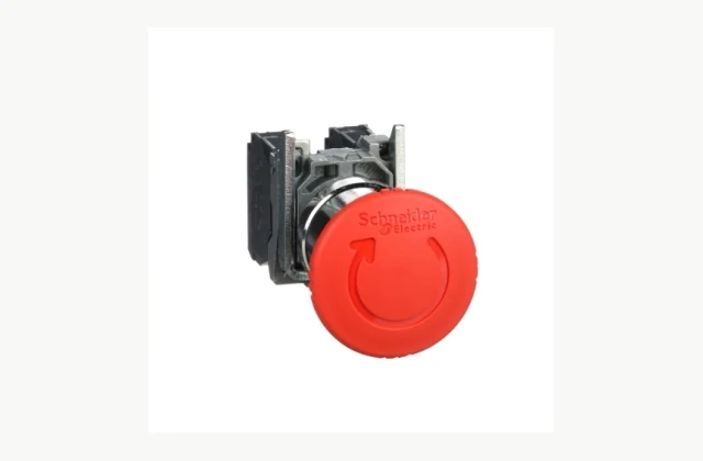
Shown as a configuration reference. Availability and the equipment offered for your project are confirmed separately.
Begin with the required protective function
An emergency stop device is one component within a machine’s control and protective arrangements. The risk assessment and applicable design requirements determine what the complete function must achieve. Identify the machine, hazards, intended device locations and responsible engineer. Buying a red mushroom actuator does not by itself establish a validated emergency stop system. Keep equipment selection connected to the machine design rather than ask a component supplier to guarantee safety from a photograph.
Identify the exact actuator and release action
Push action, latching and the selected release method affect the operator interface and component choice. Specify the intended arrangement, visibility and access in the actual machine. The Schneider Harmony XB4BS8445 reference is a particular latching turn-release assembly; another actuator or contact package should not inherit that description. Confirm the full part number and supplied components, especially where heads, mounting collars and contact blocks can also be ordered separately.
Match contact blocks to the control design
The responsible circuit design determines required contact types, number and behavior. Check the exact contact assembly, terminal arrangement and supporting manufacturer information. The reference component’s listed NC and NO arrangement describes that part, not every product in the range or a complete circuit architecture. Ask the engineer to verify any relevant direct-opening or other functional requirements against the selected part’s evidence. Similar mounting dimensions do not establish equivalent contact behavior.
| Selection issue | Information to specify |
|---|---|
| Function | Machine, risk-assessment requirements and responsible engineer. |
| Operator | Actuator, latching, release action and accessible position. |
| Contacts | Exact blocks, behavior, terminals and design evidence. |
| Installation | Panel dimensions, seals, environment and accessories. |
| System behavior | Monitoring, reset and restart requirements. |
| Validation | Completed-function records and exact replacement identity. |
Assess mounting and environmental exposure
Provide panel opening, thickness, available rear space and the installation position. Check guards or enclosures where they form part of the design and consider cleaning, dust, moisture, vibration and access. A component protection rating can have defined assembly conditions and should not be transferred automatically to the finished panel. Identify labels, seals and accessories and ensure the installed operator remains visible and accessible for the machine’s intended use.
Define reset, restart and diagnostics through the system
The machine-control design must address what happens after actuation and release, including reset and restart behavior. Clarify monitoring and diagnostic requirements with the responsible engineer. A mechanically released button does not alone define the machine’s next action. Avoid treating an available auxiliary contact as proof of a particular diagnostic or performance level. The selected device and the rest of the circuit need to be evaluated together under the approved validation process.
Validate the installed assembly and retain records
Acceptance should check the ordered part, mounting, identification and integration in the machine through the competent engineer’s procedure. Retain component data and the completed function’s validation records, not just an individual-device certificate. Maintenance staff need exact replacement identification because a visually similar actuator may have a different contact arrangement or release action. Define inspection and replacement responsibilities so later servicing preserves the approved design rather than introduces an unassessed substitute.
Bound OEM/ODM around the protective design
Labels, enclosure organization or selected mechanical interfaces may be reviewed. Changes to actuator, latching, contact or protective behavior require engineering and appropriate evidence. Provide the machine’s specified function with the brief and identify who validates the modified arrangement. Private labeling must preserve component traceability and cannot confer a machine-level safety claim. Reference-brand imagery does not establish authorization to copy the device or imply performance of an altered control system.
What should your emergency stop device RFQ include?
- Function: Machine, risk-assessment requirements and responsible engineer.
- Operator: Actuator, latching, release action and accessible position.
- Contacts: Exact blocks, behavior, terminals and design evidence.
- Installation: Panel dimensions, seals, environment and accessories.
- System behavior: Monitoring, reset and restart requirements.
- Validation: Completed-function records and exact replacement identity.
- Destination, site conditions and delivery access
- Installation boundary, utilities and connection drawings
- Acceptance procedure, documentation and training scope
- OEM/ODM changes: interface, material, branding or new design; written engineering feasibility required
Need OEM / ODM customization?
Submit branding, packaging, configuration or engineering requirements for this equipment. Include the target market, initial and annual quantities, required changes and acceptance criteria.
Customization feasibility, permitted branding, development responsibilities, minimum quantity, cost and lead time are reviewed for the proposed supplier and configuration before a quotation is confirmed.
Frequently asked questions
Does a red emergency-stop button create a complete safety function?
No. It is a component within a machine’s protective control design. The responsible engineer must define and validate the required behavior with the rest of the system. Appearance, color or a component certificate alone does not establish the completed machine’s emergency-stop performance.
Are actuator heads and contact blocks always supplied together?
Not necessarily. Product ranges can offer individual components and complete assemblies. Confirm the full part number and included head, mounting and contact equipment. A photograph of an assembled example does not establish that every item is included in a component-only order.
Can a similar-looking contact block be substituted?
A substitution needs engineering review of contact type, behavior, terminals and supporting evidence. Mechanical fit is insufficient. Retain exact component identification so maintenance does not replace an approved assembly with a visually similar part that changes the intended protective control arrangement.
Does the device rating automatically apply to a finished panel?
No automatic transfer should be assumed. Mounting, seals, accessories and enclosure conditions can affect the installed arrangement. Provide panel and environmental details and check the manufacturer’s applicable conditions with the responsible designer rather than infer complete-panel suitability from one component’s description.
What should be checked about reset and restart?
Have the responsible engineer define the machine’s response after actuation and release, including monitoring and restart conditions. Mechanical release alone does not specify system behavior. Validate the complete function through the approved procedure rather than treat a contact arrangement as evidence of the machine’s next action.
Can emergency-stop assemblies be customized through OEM/ODM?
Labels and selected interfaces can be reviewed, but changes affecting actuator, contacts or latching require engineering and appropriate evidence. Identify who validates the resulting protective function and preserve traceability. A customized or privately branded component cannot automatically inherit the reference device’s or machine’s performance claims.
Reference information
- Schneider Electric Harmony XB4BS8445 official product reference
- Schneider Electric Harmony XB4BS8445 official technical or family reference
Reference data and images explain equipment configurations. IndustryApex engineers confirm the offered model, specification and commercial scope in your project quotation.