
Choose an IO-Link master from the controller network and a complete field-device schedule. Check each port class, power requirement, connector and installation condition, then verify how process data and diagnostics reach the PLC. Engineering files, parameter management and replacement behavior belong in acceptance. State any separate IT data requirements and access boundaries. OEM/ODM requests should identify cable, enclosure or software changes for feasibility review; manufacturer examples establish reference designs rather than supply relationships.
Connect intelligent sensors and actuators using an IO-Link master matched to your PLC network, port power and machine environment. Compare device mapping, engineering files, diagnostics and replacement procedures, with clear requirements for cable kits, configuration services and OEM or ODM integration.
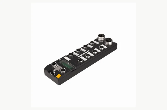
Shown as a configuration reference. Availability and the equipment offered for your project are confirmed separately.
Map the device layer and controller network first
An IO-Link master connects individual compatible field devices to a higher-level automation network. It is the interface between sensor or actuator connections and the controller architecture, rather than a replacement for every part of that architecture. Begin with the PLC type, network protocol and a device list showing the information required from each connection.
Identify which signals are needed cyclically for machine operation and which parameters or diagnostics are used during setup or maintenance. This distinction influences the integration effort and the controller program. State whether the project is a new machine or a retrofit, and provide the existing network diagram. A master with the right connector count can still be unsuitable if the controller interface or device-data mapping is wrong.
Match port class, power and connectors to each device
Prepare a port schedule before choosing a module. For every sensor, valve interface or other device, record its IO-Link designation, supply requirements, connector pinout and installation location. Class A and Class B connections have different power arrangements; confirm the requirements of both the master and the connected device rather than relying on a visually similar M12 connector.
Calculate the complete power budget for the proposed arrangement, including simultaneous actuator demand and voltage drop through the installed cables. Check supply grouping, protection and restart behavior in the exact instructions. Also identify devices that will use ordinary digital input or output modes. The resulting schedule should make unused capacity and reserved ports visible without confusing them with verified capability for an unspecified future actuator.
Review the installation environment and network functions
Decide whether the master belongs in a cabinet or directly on the machine. Specify exposure to coolant, washdown, dust, vibration, sunlight and ambient temperature as applicable. Match the enclosure, cable assemblies, protective caps and mounting position as a complete installation. A protection claim on the module alone does not define every connector assembly in service.
Network features should be selected from the actual topology and operating requirement. Confirm controller protocol, addressing, recovery behavior and any redundancy requirement against the exact proposed model. TURCK TBEN-L5-8IOL is an official example of a multiprotocol master; the reference image does not mean that every IO-Link master supports the same protocols or that all protocol combinations operate simultaneously.
Compare engineering deliverables rather than port count alone
Request the configuration files and engineering example needed for the actual PLC environment. The device IODD describes its data and parameters, while controller integration also depends on the master and its network files. Ask the supplier to demonstrate the agreed process values, status information and parameter operations in the intended engineering software.
Use an integration matrix to compare offers. It should identify responsibilities for device configuration, controller programming and higher-level data use. The following table provides a practical starting point; the required evidence should be agreed for the specific machine.
| Integration area | Define in the RFQ | Evidence for acceptance |
|---|---|---|
| Controller network | Protocol, topology and PLC environment | Project file and live data exchange |
| Device ports | Device identity, class and supply needs | Port schedule and connection test |
| Process values | Data format, units and valid-state behavior | PLC mapping and test records |
| Replacement | Parameter backup and restoration procedure | Witnessed compatible device change |
| IT data use | Required interface and access boundary | Documented data path and access settings |
Test diagnostics, replacement and ownership of the project
A commissioning test should exercise more than a changing sensor value. Include a disconnected device, an unexpected device identity and the agreed recovery sequence. Confirm how invalid data is indicated to the controller and what the machine program does with it. These behaviors need to be designed into the application rather than inferred from an indicator light.
Demonstrate parameter backup and replacement with a compatible device if that function is part of the purchase. Keep a copy of the accepted configuration, software versions and device descriptions. Define who can change parameters and how configuration changes are recorded. Where data leaves the control network, agree segmentation and access arrangements with the responsible automation and IT teams.
Scope OEM and ODM integration requests clearly
OEM requirements may include a labeled harness kit, documentation, a preconfigured port map or machine-specific packaging. ODM development may concern an enclosure, interface board or software integration. Provide the complete electrical and data requirements, intended annual use and destination so that a manufacturer or integrator can distinguish configuration work from new development.
Do not assume that a branded reference product can be privately labeled or modified. Changes to power distribution, connectors or communication behavior need their own feasibility review and validation. Ask for a response separating standard hardware, engineering services, accessories and development evidence. Send the controller model, device list and port schedule with the inquiry to receive a proposal that can be checked against the machine.
What should your io-link master RFQ include?
- PLC model, engineering software and required controller protocol
- Network topology, addressing and recovery requirements
- Complete IO-Link device list and available IODD files
- Port-by-port Class A/Class B and digital I/O schedule
- Device supply currents and simultaneous actuator demand
- Connector pinouts, cable lengths and harness requirements
- Mounting location, media exposure and ambient conditions
- Process-data mapping, diagnostics and invalid-data behavior
- Parameter backup, replacement test and project-file handover
- OEM harness/labeling or ODM enclosure/interface development requirements
Need OEM / ODM customization?
Submit branding, packaging, configuration or engineering requirements for this equipment. Include the target market, initial and annual quantities, required changes and acceptance criteria.
Customization feasibility, permitted branding, development responsibilities, minimum quantity, cost and lead time are reviewed for the proposed supplier and configuration before a quotation is confirmed.
Frequently asked questions
Is an IO-Link master a replacement for a PLC?
An IO-Link master connects field devices to higher-level automation. Its role does not automatically include the machine-control functions performed by a PLC. Some products have additional logic features, but these must be checked separately. Define the controller architecture and required master functions before selecting hardware.
What is the difference between Class A and Class B ports?
The port classes use different power arrangements, with Class B providing an additional separated supply for suitable devices. Check the exact device and master documentation, connector pinout and current requirements. Similar connector shapes do not establish electrical compatibility or prove that a particular actuator can be powered.
Can IO-Link devices from different manufacturers be connected?
IO-Link provides a standardized device connection, but the actual device revision, power requirements and data integration still need checking. Obtain the device description and relevant engineering files, then test the intended measurements and parameters. Manufacturer independence does not remove the need for application-level compatibility validation.
Does the IODD file complete PLC integration by itself?
The IODD describes the IO-Link device and helps configuration tools interpret its functions. PLC integration also depends on the master, controller protocol and associated engineering files. Request an example project for the intended controller and demonstrate data formats, valid-state signals and parameter operations before acceptance.
What should be tested when replacing a sensor?
Test the agreed device-identification and parameter-restoration procedure with a compatible replacement. Verify that measurements, units, switching behavior and diagnostics return as intended. Record any operator steps and controller response while data is unavailable. Keep the accepted configuration and device descriptions for future maintenance.
Can an IO-Link master be supplied for OEM or ODM projects?
Submit labeling, harness, preconfiguration, enclosure or software requirements for feasibility review. Standard hardware integration and changes to electronic design are different scopes. The responding manufacturer must confirm what it can support and what validation is needed; reference product images do not establish private-label availability.
Reference information
- TURCK TBEN-L5-8IOL product and technical data
- ifm IO-Link technology, ports and IODD guide
- TURCK decentralized control of valve interfaces
Reference data and images explain equipment configurations. IndustryApex engineers confirm the offered model, specification and commercial scope in your project quotation.