
Multi component injection molding combines two or more materials or colors in one molded part. Tool indexing, material compatibility and coordinated shots distinguish it from a single-material molding cell. Compare injection-unit arrangement, rotating/indexing tooling and transfer concepts. Extra injection capacity does not establish acceptable bonding, balanced filling or a reliable complete cycle. Trial each shot and the finished assembly for dimensions, interface quality, appearance and repeatability. Include color/material changes, indexing faults and restart of partially completed cycles. Project-specific OEM branding and ODM engineering should be described in the inquiry and reviewed for feasibility before an offer is finalized.
Multi component injection molding combines two or more materials or colors in one molded part. Tool indexing, material compatibility and coordinated shots distinguish it from a single-material molding cell. Start with part and multi-material interface drawing and material grades colors and shrinkage, then compare the complete configured system and a documented acceptance trial.
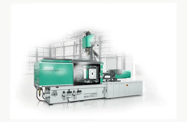
Shown as a configuration reference. Availability and the equipment offered for your project are confirmed separately.
Define the multi component injection molding system process boundary
Multi component injection molding combines two or more materials or colors in one molded part. Tool indexing, material compatibility and coordinated shots distinguish it from a single-material molding cell.
Use this boundary when reviewing proposals. The adjacent process must be named explicitly, so an inexpensive machine-only offer is not confused with a complete working installation.
Part and multi-material interface drawing: describe the real input
Provide part geometry, material pairing, bonding or separation needs, colors and inserts. Include shrinkage differences, thermal sensitivity and requirements at the interface between materials.
Submit representative samples, drawings or a production record where available. Identify normal variation and the most demanding condition, because an easy demonstration does not establish performance across every intended application.
Compare multi component injection molding system configurations
Compare injection-unit arrangement, rotating/indexing tooling and transfer concepts. Extra injection capacity does not establish acceptable bonding, balanced filling or a reliable complete cycle.
Ask bidders to mark their selected arrangement and alternatives on the offer. Keep the stated assumptions with the quotation, and distinguish useful output from an unloaded cycle or another nominal catalog maximum.
Integrate the multi component injection molding system with adjoining equipment
Define material preparation, multiple feeds, mold movement, robot handling and inspection. Each component and index position needs traceable settings and synchronized permission before the next shot.
A line layout should show transfer directions, control handshakes and responsibility for each connecting part. Include the consequences of upstream stoppages and downstream unavailability in the review.
| Decision | Requirement to define | Evidence in the offer |
|---|---|---|
| Application | Provide part geometry, material pairing, bonding or separation needs, colors and inserts. | Agreed input envelope and exclusions |
| Configuration | Compare injection-unit arrangement, rotating/indexing tooling and transfer concepts. | Selected arrangement and engineering assumptions |
| Integration | Define material preparation, multiple feeds, mold movement, robot handling and inspection. | Interface drawing and responsibility boundary |
| Installation | Review machine/tool envelope, utilities, access and routing for several material circuits. | Site layout and utility scope |
| Acceptance | Trial each shot and the finished assembly for dimensions, interface quality, appearance and repeatability. | Recorded application trial and sampling method |
| Service | Maintain injection units, valves, seals, indexing mechanisms and material identification. | Identified wear components and maintenance access |
Plan multi component injection molding system installation and utilities
Review machine/tool envelope, utilities, access and routing for several material circuits. Maintain protection around moving molds and transfer devices as one integrated cell.
Confirm the destination electrical supply and the services actually available during production. Include delivery access, placement, commissioning and operator training in the installed scope, with exclusions made visible before ordering.
Write a multi component injection molding system acceptance protocol
Trial each shot and the finished assembly for dimensions, interface quality, appearance and repeatability. Include color/material changes, indexing faults and restart of partially completed cycles.
Agree which material, recipe or load is used, who measures the result and how unsuccessful checks are resolved. Preserve the tested configuration with the report so the delivered machine can be compared with the accepted demonstration.
Service the configured multi component injection molding system
Maintain injection units, valves, seals, indexing mechanisms and material identification. Tool or feed changes should be checked against both individual shots and the final combined part.
Request a parts list and the documentation needed by the receiving maintenance team. Separate preventive service, consumables, remote assistance and site visits in the commercial scope; confirm the destination support arrangement for the selected supplier.
OEM branding and ODM engineering for multi component injection molding system
Unit positions, mold indexing, controls and automation may be engineered. New material combinations require bonding and molding trials; customization does not imply universal polymer compatibility.
OEM requests may cover branding, packaging and agreed manuals for equipment supplied under an appropriate arrangement. ODM is an engineering discussion with defined drawings, change approval, verification and spare-part identification. Neither option implies authorization to relabel the reference manufacturer shown here.
ARBURG ALLROUNDER MORE 1600 multi-component injection machine is shown as a technical configuration reference. The image and reference names do not establish IndustryApex inventory, authorized dealership, equivalent performance or availability. Confirm the offered manufacturer, exact configuration and commercial responsibilities for your project.
Compare the adjoining process before fixing the supply boundary:
What should your multi component injection molding system RFQ include?
- Part and multi-material interface drawing
- Material grades colors and shrinkage
- Bonding separation appearance targets
- Injection unit indexing arrangement
- Shot sequencing and traceability
- Drying robot inspection interfaces
- Tool envelope utilities guarding
- Interface index restart-quality trials
- Unit seal index valve service
- OEM parts ODM multi-shot tooling
Need OEM / ODM customization?
Submit branding, packaging, configuration or engineering requirements for this equipment. Include the target market, initial and annual quantities, required changes and acceptance criteria.
Customization feasibility, permitted branding, development responsibilities, minimum quantity, cost and lead time are reviewed for the proposed supplier and configuration before a quotation is confirmed.
Frequently asked questions
What information is needed to select a multi component injection molding system?
Provide part geometry, material pairing, bonding or separation needs, colors and inserts. Include shrinkage differences, thermal sensitivity and requirements at the interface between materials. Supply this information for the actual application, including the normal variation. It gives suppliers a defined selection envelope and makes assumptions in competing quotations visible.
Which configuration choices matter for a multi component injection molding system?
Compare injection-unit arrangement, rotating/indexing tooling and transfer concepts. Extra injection capacity does not establish acceptable bonding, balanced filling or a reliable complete cycle. Ask for the selected arrangement in writing with its application limits, so the trial and delivered configuration refer to the same equipment.
What equipment belongs around a multi component injection molding system?
Define material preparation, multiple feeds, mold movement, robot handling and inspection. Each component and index position needs traceable settings and synchronized permission before the next shot. Request an interface drawing and identify who supplies the connecting components, controls and commissioning work rather than relying on a broad turnkey description.
What installation requirements should be reviewed for a multi component injection molding system?
Review machine/tool envelope, utilities, access and routing for several material circuits. Maintain protection around moving molds and transfer devices as one integrated cell. Check the receiving site early, including services during production and clearances during maintenance. Record responsibility for the installation and local engineering reviews.
How should a multi component injection molding system be accepted and maintained?
Trial each shot and the finished assembly for dimensions, interface quality, appearance and repeatability. Include color/material changes, indexing faults and restart of partially completed cycles. Maintain injection units, valves, seals, indexing mechanisms and material identification. Tool or feed changes should be checked against both individual shots and the final combined part.
Can a multi component injection molding system support OEM or ODM requirements?
Unit positions, mold indexing, controls and automation may be engineered. New material combinations require bonding and molding trials; customization does not imply universal polymer compatibility. Describe OEM branding and documentation separately from ODM mechanical, process or control changes. Feasibility, engineering ownership and acceptance evidence must be confirmed for the proposed supplier and configuration.
Reference information
- ARBURG — Multi-component injection moulding technology
- ARBURG — ALLROUNDER MORE electric two-injection-unit machine
Reference data and images explain equipment configurations. IndustryApex engineers confirm the offered model, specification and commercial scope in your project quotation.