
OEM ODM disc mower conditioner projects require buyer drawings with mounting dimensions, PTO interface specifications, hydraulic connections, electrical integration points, production quantities, branding locations, and validation criteria. IndustryApex engineers work with manufacturers to adapt cutter bar designs, conditioner systems, frame configurations and control interfaces to project requirements.
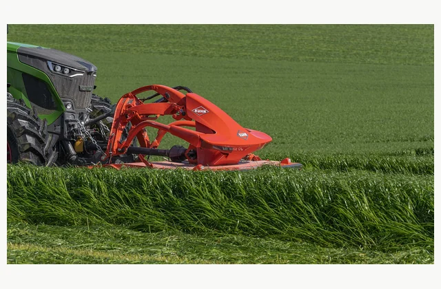
Shown as a configuration reference. Availability and the equipment offered for your project are confirmed separately.
Disc mower conditioner OEM ODM customization adapts frame geometry, cutting systems, conditioning mechanisms and control interfaces to buyer specifications. Projects typically begin with buyer drawings that define mounting points, power take-off compatibility, hydraulic circuit integration, and branding placement. Manufacturers adjust cutter bar width, disc spacing, conditioner roller or tine configurations, and swath formation geometry based on the specified crop types, working conditions and tractor interface requirements.
Buyer Drawings and Interface Specifications
OEM projects require detailed drawings that specify mounting bracket positions, three-point hitch category, PTO shaft length and guarding, hydraulic quick-coupler types, and electrical connector standards. Disc mower conditioners incorporate multiple movement axes—the mowing unit pivots vertically and laterally to follow ground contours—so mounting kinematics must align with the buyer’s tractor population and operational terrain. Reference designs like the KUHN FC series use kinematics that incorporate two robust lower links mounted on large ball joints [S1], but custom projects may require different pivot locations, link lengths or suspension characteristics for non-standard tractor interfaces or specialized applications.
Hydraulic integration includes lift cylinder specifications, pressure settings for hydro-pneumatic suspension systems, and optional circuits for folding side guards or adjusting conditioning intensity. Electrical connections support control terminals, safety interlocks and optional automation features. Buyers should specify connector standards, voltage requirements, and CAN bus protocols if machine data integration is required. PTO input speed, shaft size, and overload protection must match the specified tractor model range.
Cutter Bar and Conditioning System Configuration
Cutter bar customization addresses working width, disc count, disc spacing, skid design, and drive train layout. Manufacturers can adjust disc overlap patterns, cutting angles, and housing attachment methods to suit specific crop conditions or debris environments. Conditioning system selection—steel finger rotors versus polyurethane roller pairs—depends on the target crop types and buyer operational preferences. Each system requires different drive configurations, adjustment mechanisms, and frame clearances.
Buyers must specify crop types, maturity stages at harvest, typical yield ranges, field conditions, and expected throughput. These inputs determine conditioner rotor diameter, tine geometry or roller tread profiles, drive ratios, and adjustment ranges. Custom projects may require non-standard conditioning intensities, alternative swath formation patterns, or specialized materials for abrasive or corrosive crop environments. Frame strength, bearing specifications, and drivetrain components scale with the specified working width and power transmission requirements.
Branding and Production Quantities
OEM branding includes embossed logos on frame castings, painted graphics on sheet metal components, adhesive decals, and serialized data plates. Buyers provide brand artwork, color specifications, placement locations, and durability requirements. Tooling costs for custom castings, paint masks, or embossing dies are typically amortized across production quantities, so branding complexity affects minimum order thresholds. Adhesive decals offer lower tooling costs but may have shorter field life in high-UV or abrasive environments.
Production quantities influence component sourcing, assembly line setup, quality control sampling plans, and spare parts inventory commitments. Manufacturers distinguish prototype quantities for field validation, pilot production runs, and full-scale series production. Buyers should forecast annual volumes, order release schedules, and anticipated model life to support supplier capacity planning and component procurement. Long component lead times for castings, forgings, or specialized bearings may require advance commitments before final design approval.
Validation Criteria and Acceptance Boundaries
Project-specific validation defines performance acceptance criteria, durability testing protocols, and quality inspection procedures. Buyers specify cutting quality standards, conditioning uniformity targets, ground pressure limits, and acceptable vibration or noise levels. Durability validation may include specified operating hour targets, obstacle impact testing, or accelerated wear protocols for critical components like disc bearings or conditioner drives.
Acceptance testing should occur under conditions representative of the buyer’s target market—crop types, field conditions, and operational practices. Prototype validation identifies design adjustments needed before tooling commitment. Buyers and manufacturers agree on test duration, sample size, measurement methods, and pass/fail criteria in advance. Safety-critical elements like shear protection systems [S1], hydraulic cylinder mounting strength, and PTO guarding require specific impact or load testing protocols supervised by qualified engineering personnel.
Engineering Collaboration and Documentation
Successful OEM projects depend on iterative engineering dialogue. Manufacturers provide feasibility assessments, recommend component selections, identify design constraints, and propose alternative approaches when buyer specifications conflict with manufacturing capabilities or cost targets. Buyers provide application context, operational constraints, and market-specific requirements that guide design tradeoffs. Regular design reviews, prototype inspections, and validation result discussions keep projects aligned with performance and schedule targets.
Final documentation includes approved manufacturing drawings, bill of materials, assembly procedures, quality control plans, spare parts catalogs, and operator manuals with buyer branding. Intellectual property agreements define ownership of custom designs, tooling, and technical documentation. After-sales support arrangements—spare parts availability, technical assistance, and warranty administration—require clear definition before production commitment.
IndustryApex Engineering Support
IndustryApex professional engineers work directly with buyers to develop OEM ODM disc mower conditioner specifications, coordinate manufacturer dialogue, review design proposals, and oversee validation planning. The team assists with interface definition, component selection tradeoffs, branding integration, and acceptance criteria development. For project discussion and equipment solution proposals, contact IndustryApex engineering to review your application requirements and production objectives.
Further guidance on custom agricultural equipment projects is available athttps://industryapex.com/oem-odm/. The canonical product guide is at https://industryapex.com/equipment/disc-mower-conditioners/.
OEM Specification Worksheet
| Specification Category | Buyer Input Required |
|---|---|
| Mounting Interface | Three-point hitch category, mounting bracket positions, frame dimensions, pivot geometry, ground clearance requirements |
| Power Transmission | PTO input speed and shaft size, hydraulic flow and pressure specifications, electrical voltage and connector standards |
| Cutter Bar | Working width, disc count and spacing, cutting height range, skid material, disc drive configuration, obstacle protection requirements |
| Conditioning System | Conditioner type (steel finger or polyurethane roller), rotor diameter, conditioning intensity adjustment range, crop types and conditions |
| Operational Parameters | Target crop types, typical yield, field terrain characteristics, expected ground speed, swath width and formation pattern |
| Branding | Logo artwork and placement locations, paint color specifications, decal or embossing requirements, serialization format |
| Production | Prototype quantity, pilot production volume, annual series production forecast, delivery schedule, model life expectancy |
| Validation | Performance acceptance criteria, durability test protocols, quality inspection sampling, test conditions and duration |
| Documentation | Drawing standards, language requirements for manuals, spare parts catalog format, intellectual property ownership terms |
Define your equipment requirements
Review the Disc mower conditioner buying guide for the complete equipment scope.
Discuss this equipment project ↗ · OEM requirements · ODM requirements. Configuration and feasibility are reviewed for your application.
Explore the Disc mower conditioner buying guide and RFQ checklist ↗
Frequently asked questions
What engineering drawings are required to begin an OEM disc mower conditioner project?
Buyers provide mounting interface drawings with three-point hitch dimensions and pivot locations, PTO shaft specifications with length and guarding requirements, hydraulic circuit diagrams showing cylinder connections and pressure ratings, electrical connector standards, and branding placement drawings. Manufacturers use these to assess feasibility, identify design constraints, and propose component selections.
How do manufacturers adapt cutter bar configurations to buyer specifications?
Manufacturers adjust working width, disc count, disc spacing patterns, cutting angle, skid design, and drive train layout based on specified crop types, field conditions, and operational requirements. Custom projects may require modified overlap geometry, specialized skid materials for rocky terrain, or alternative bearing specifications for high-hour applications. Buyers specify performance targets; manufacturers propose component solutions.
What determines minimum order quantities for custom branding?
Tooling costs for embossed castings, paint masking, or custom decals are amortized across production volumes. Complex branding with multiple embossed locations increases tooling investment and raises minimum quantities. Adhesive decals have lower tooling costs but may require more frequent field replacement. Buyers should forecast total production volumes and model life to support manufacturer capacity planning.
What validation testing occurs before series production approval?
Prototype validation tests cutting quality, conditioning uniformity, ground contour following, and component durability under specified crop and field conditions. Manufacturers and buyers agree on test duration, measurement methods, and acceptance criteria in advance. Safety-critical systems like shear protection, hydraulic mounting strength, and PTO guarding require specific load or impact testing supervised by qualified personnel.
How does conditioning system selection affect OEM project scope?
Steel finger conditioners and polyurethane roller systems require different drive configurations, frame clearances, adjustment mechanisms, and maintenance access. Buyers specify target crop types, maturity stages, and conditioning intensity preferences; manufacturers recommend system type and propose rotor dimensions, tine geometry or roller tread profiles, and drive ratio options. Each system has different throughput characteristics and power requirements.
What documentation does the manufacturer provide at project completion?
Final deliverables include approved manufacturing drawings, bill of materials, assembly procedures, quality control plans, spare parts catalogs with buyer part numbers, and operator manuals with custom branding. Intellectual property agreements define ownership of custom designs and tooling. After-sales support terms—spare parts availability, technical assistance scope, and warranty administration—are defined in the supply agreement.
Reference information
- Front mounted mower conditioners FC1025 F | KUHN
Reference data and images explain equipment configurations. IndustryApex engineers confirm the offered model, specification and commercial scope in your project quotation.