
Choose a rodless pneumatic actuator for the required travel, installed length and moving-load geometry. Review guide moments, sealing and stopping energy with the actual air circuit. Long stroke in a compact envelope does not remove the need for rigid support and suitable load guidance. Run representative minimum and maximum loads through full travel at the intended point-of-use pressure. Check smooth motion, carriage/tool deflection, end impacts and position signals. Include long-cycle warming, controlled interruption and restart, documenting support positions, guide alignment and air settings with the result. Submit the intended configuration and any OEM/ODM changes for project-specific feasibility review.
Choose a rodless pneumatic actuator for the required travel, installed length and moving-load geometry. Review guide moments, sealing and stopping energy with the actual air circuit. Long stroke in a compact envelope does not remove the need for rigid support and suitable load guidance.
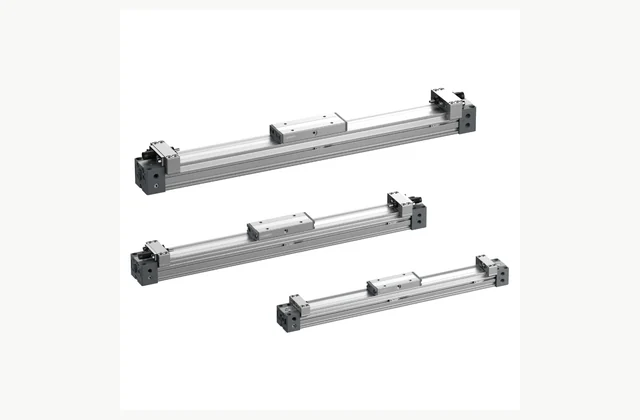
Shown as a configuration reference. Availability and the equipment offered for your project are confirmed separately.
Choose the rodless transmission concept
Mechanically coupled and magnetically coupled rodless cylinders have different operating boundaries. State the intended force, environment and carriage duty. The SMC MY1B reference uses a mechanically jointed arrangement; its characteristics should not be applied automatically to a magnetically coupled alternative.
Assess carriage moments and guidance
Provide payload, overhang and forces applied to the moving table throughout travel. Some rodless cylinders need external guides to carry these loads. Compare the selected guide arrangement and mounting with the actual moment directions rather than inferring bearing capacity from a long carriage surface.
Support the long-stroke structure
A long actuator can deflect or distort if mounted on an unsuitable frame. Define span, intermediate supports and alignment requirements using the selected model's instructions. Installed length should include fittings, end adjustment and service clearances, not only the nominal cylinder-body dimension.
Size speed and end cushioning
Supply travel time, cycle rate and moving mass with valve and tubing information. Large travel can produce substantial end energy. Confirm allowable cushioning or external absorbers and assess controlled stops; raising pressure is not a substitute for selecting adequate flow and energy capacity.
Protect the sealing band and sensing
Describe dust, chips, coolant or sticky contaminants along the stroke. Confirm covers, sealing-band care and sensor access. Position switches must indicate the required machine states, and adjustment should account for carriage stopping behavior rather than simply matching a nominal groove location.
Review air loss and maintenance recovery
Determine what happens to the carriage when pressure is lost, especially on sloped or vertical installations. Identify safe isolation and load support. Obtain sealing, guide and end-stop parts with a procedure for restoring alignment and speed after service, since the entire travel influences reliable operation.
Compare a complete rodless pneumatic actuator scope
| Decision | Information to compare |
|---|---|
| Choose the rodless transmission concept | Coupling concept, force duty, carriage motion and operating environment |
| Assess carriage moments and guidance | Payload, center of gravity, carriage moments and external/integrated guidance |
| Support the long-stroke structure | Travel, support span, intermediate supports, alignment and installed envelope |
| Size speed and end cushioning | Travel speed, valve flow, moving mass, cushions and stop energy |
| Protect the sealing band and sensing | Stroke contamination, sealing protection, switches and position-confirmation logic |
| Review air loss and maintenance recovery | Orientation, pressure-loss behavior, support, seals and post-service checks |
Plan installation and access
Align the actuator and any external guide over the full travel, using supports that do not twist the body. Keep hoses and sensor wiring outside the moving-load envelope. Guard the long swept zone and provide safe isolation and mechanical support before adjustments.
Agree acceptance evidence before ordering
Run representative minimum and maximum loads through full travel at the intended point-of-use pressure. Check smooth motion, carriage/tool deflection, end impacts and position signals. Include long-cycle warming, controlled interruption and restart, documenting support positions, guide alignment and air settings with the result.
Define OEM/ODM engineering boundaries
OEM carriage adapters, covers and approved stroke variants can be reviewed. ODM band sealing, coupling or guide changes require mechanical and endurance testing. The reference image identifies a particular rodless family and does not confer its load ratings or manufacturer authorization on another design.
What should your rodless pneumatic actuator RFQ include?
- Coupling concept, force duty, carriage motion and operating environment
- Payload, center of gravity, carriage moments and external/integrated guidance
- Travel, support span, intermediate supports, alignment and installed envelope
- Travel speed, valve flow, moving mass, cushions and stop energy
- Stroke contamination, sealing protection, switches and position-confirmation logic
- Orientation, pressure-loss behavior, support, seals and post-service checks
- Destination, working environment, access and delivery constraints
- Installation responsibility, utilities and connection drawings
- Acceptance samples, documented test method, operator training and maintenance scope
- OEM/ODM changes requested: identification, tooling, interfaces or new design; engineering feasibility to be confirmed
Need OEM / ODM customization?
Submit branding, packaging, configuration or engineering requirements for this equipment. Include the target market, initial and annual quantities, required changes and acceptance criteria.
Customization feasibility, permitted branding, development responsibilities, minimum quantity, cost and lead time are reviewed for the proposed supplier and configuration before a quotation is confirmed.
Frequently asked questions
How do I choose the rodless transmission concept?
Mechanically coupled and magnetically coupled rodless cylinders have different operating boundaries. State the intended force, environment and carriage duty. The SMC MY1B reference uses a mechanically jointed arrangement; its characteristics should not be applied automatically to a magnetically coupled alternative.
How do I assess carriage moments and guidance?
Provide payload, overhang and forces applied to the moving table throughout travel. Some rodless cylinders need external guides to carry these loads. Compare the selected guide arrangement and mounting with the actual moment directions rather than inferring bearing capacity from a long carriage surface.
How do I support the long-stroke structure?
A long actuator can deflect or distort if mounted on an unsuitable frame. Define span, intermediate supports and alignment requirements using the selected model's instructions. Installed length should include fittings, end adjustment and service clearances, not only the nominal cylinder-body dimension.
How do I size speed and end cushioning?
Supply travel time, cycle rate and moving mass with valve and tubing information. Large travel can produce substantial end energy. Confirm allowable cushioning or external absorbers and assess controlled stops; raising pressure is not a substitute for selecting adequate flow and energy capacity.
How do I protect the sealing band and sensing?
Describe dust, chips, coolant or sticky contaminants along the stroke. Confirm covers, sealing-band care and sensor access. Position switches must indicate the required machine states, and adjustment should account for carriage stopping behavior rather than simply matching a nominal groove location.
How do I review air loss and maintenance recovery?
Determine what happens to the carriage when pressure is lost, especially on sloped or vertical installations. Identify safe isolation and load support. Obtain sealing, guide and end-stop parts with a procedure for restoring alignment and speed after service, since the entire travel influences reliable operation.
Reference information
- SMC MY1B official product reference
- SMC rodless pneumatic actuator official family or technical reference
Reference data and images explain equipment configurations. IndustryApex engineers confirm the offered model, specification and commercial scope in your project quotation.