
Select a vacuum ejector from workpiece leakage, pickup volume, required evacuation time and compressed-air demand. Match suction cups, switches and release control as one handling circuit, then test the real parts and failure response rather than comparing ultimate vacuum alone. Pick representative best and worst surfaces through the full motion cycle at minimum agreed supply pressure. Record evacuation, achieved cup vacuum, release time and air demand using agreed methods. Verify partial-seal and empty-pickup responses and document cup, hose and threshold settings with the accepted parts. Submit the intended configuration and any OEM/ODM changes for project-specific feasibility review.
Select a vacuum ejector from workpiece leakage, pickup volume, required evacuation time and compressed-air demand. Match suction cups, switches and release control as one handling circuit, then test the real parts and failure response rather than comparing ultimate vacuum alone.
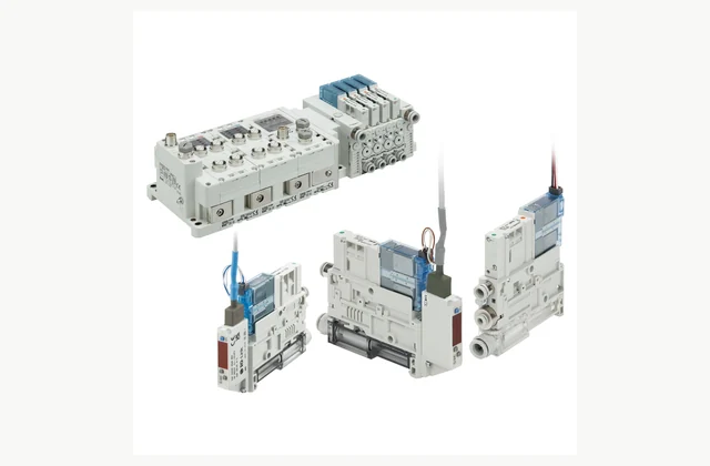
Shown as a configuration reference. Availability and the equipment offered for your project are confirmed separately.
Characterize the workpiece leakage
Provide porosity, roughness, curvature and any holes, seams or coatings in the pickup area. A porous carton and a sealed sheet require different suction behavior. Test actual surfaces because a high no-flow vacuum rating does not establish holding on a continuously leaking workpiece.
Size evacuation for the complete volume
Include cup volume, hoses, fittings and the distance to the ejector. Required pickup time depends on suction flow across the operating vacuum range. A compact ejector placed far from the cup may spend much of the cycle evacuating unnecessary tubing instead of establishing the grip.
Assess cup holding and dynamic loads
Suction force depends on effective sealed area and achieved pressure difference at the cup. Include acceleration, orientation and shear conditions with suitable engineering margins. The ejector alone does not determine safe holding, so review cup layout and the part's tendency to peel or flex.
Review compressed-air consumption
Specify available inlet pressure, simultaneous ejectors and duty cycle. Compare continuous suction and any air-saving strategy under the real leakage conditions. A saving mode that works on a sealed demonstration part may cycle excessively or fail to maintain the intended vacuum on porous production material.
Confirm grip sensing and release
Define switch thresholds, response, machine handshake and blow-off requirements. Check that release is quick enough without moving or damaging the workpiece. Include empty pickup, partial seal and blocked filter tests; a switch near the ejector may not reveal every problem at a distant suction cup.
Protect filters and plan loss-of-air behavior
Dust can reduce suction and alter evacuation time. Specify filter access and replacement criteria along with the required air quality. Determine retained-load or controlled-release behavior through the machine risk assessment; standard ejector operation is not inherently a safe load-holding system after air loss.
Compare a complete vacuum ejector scope
| Decision | Information to compare |
|---|---|
| Characterize the workpiece leakage | Part surface, porosity, leakage paths, curvature and pickup area |
| Size evacuation for the complete volume | Cup/tube volume, hose length, target vacuum and evacuation time |
| Assess cup holding and dynamic loads | Cup layout, effective area, part mass, acceleration and peel/shear loads |
| Review compressed-air consumption | Supply pressure, ejector count, leakage, duty cycle and air-saving behavior |
| Confirm grip sensing and release | Vacuum thresholds, switch location, blow-off and abnormal-pickup response |
| Protect filters and plan loss-of-air behavior | Suction filters, air quality, maintenance access and air-loss strategy |
Plan installation and access
Mount the ejector and sensors where hose volume and service access are appropriate for the handling task. Support tubing and avoid restrictions or leaks in the vacuum path. Provide accessible air isolation and guard the area where an unsuccessfully held part could fall.
Agree acceptance evidence before ordering
Pick representative best and worst surfaces through the full motion cycle at minimum agreed supply pressure. Record evacuation, achieved cup vacuum, release time and air demand using agreed methods. Verify partial-seal and empty-pickup responses and document cup, hose and threshold settings with the accepted parts.
Define OEM/ODM engineering boundaries
OEM cup interfaces, mounting and control integration can be reviewed. ODM nozzle, valve, filter or sensing changes require airflow and handling validation. Reference imagery does not establish stock, a manufacturer relationship or safe handling capability for an alternative assembly.
What should your vacuum ejector RFQ include?
- Part surface, porosity, leakage paths, curvature and pickup area
- Cup/tube volume, hose length, target vacuum and evacuation time
- Cup layout, effective area, part mass, acceleration and peel/shear loads
- Supply pressure, ejector count, leakage, duty cycle and air-saving behavior
- Vacuum thresholds, switch location, blow-off and abnormal-pickup response
- Suction filters, air quality, maintenance access and air-loss strategy
- Destination, working environment, access and delivery constraints
- Installation responsibility, utilities and connection drawings
- Acceptance samples, documented test method, operator training and maintenance scope
- OEM/ODM changes requested: identification, tooling, interfaces or new design; engineering feasibility to be confirmed
Need OEM / ODM customization?
Submit branding, packaging, configuration or engineering requirements for this equipment. Include the target market, initial and annual quantities, required changes and acceptance criteria.
Customization feasibility, permitted branding, development responsibilities, minimum quantity, cost and lead time are reviewed for the proposed supplier and configuration before a quotation is confirmed.
Frequently asked questions
How do I characterize the workpiece leakage?
Provide porosity, roughness, curvature and any holes, seams or coatings in the pickup area. A porous carton and a sealed sheet require different suction behavior. Test actual surfaces because a high no-flow vacuum rating does not establish holding on a continuously leaking workpiece.
How do I size evacuation for the complete volume?
Include cup volume, hoses, fittings and the distance to the ejector. Required pickup time depends on suction flow across the operating vacuum range. A compact ejector placed far from the cup may spend much of the cycle evacuating unnecessary tubing instead of establishing the grip.
How do I assess cup holding and dynamic loads?
Suction force depends on effective sealed area and achieved pressure difference at the cup. Include acceleration, orientation and shear conditions with suitable engineering margins. The ejector alone does not determine safe holding, so review cup layout and the part's tendency to peel or flex.
How do I review compressed-air consumption?
Specify available inlet pressure, simultaneous ejectors and duty cycle. Compare continuous suction and any air-saving strategy under the real leakage conditions. A saving mode that works on a sealed demonstration part may cycle excessively or fail to maintain the intended vacuum on porous production material.
How do I confirm grip sensing and release?
Define switch thresholds, response, machine handshake and blow-off requirements. Check that release is quick enough without moving or damaging the workpiece. Include empty pickup, partial seal and blocked filter tests; a switch near the ejector may not reveal every problem at a distant suction cup.
How do I protect filters and plan loss-of-air behavior?
Dust can reduce suction and alter evacuation time. Specify filter access and replacement criteria along with the required air quality. Determine retained-load or controlled-release behavior through the machine risk assessment; standard ejector operation is not inherently a safe load-holding system after air loss.
Reference information
- SMC ZK2A official product reference
- SMC vacuum ejector official family or technical reference
Reference data and images explain equipment configurations. IndustryApex engineers confirm the offered model, specification and commercial scope in your project quotation.