
Plan a pneumatic valve manifold from the machine's complete valve list, pressure zones and control network. Match station functions, common exhaust and electrical capacity, then verify simultaneous actuator demand and fault diagnosis with the proposed valve island configuration. Exercise all stations individually and in the planned simultaneous groups. Check pressure drop, travel timing, leaks, diagnostics and communication restart. Verify the delivered physical station order against the controller map and demonstrate controlled valve replacement, retaining the final assembly code and configuration backup. Submit the intended configuration and any OEM/ODM changes for project-specific feasibility review.
Plan a pneumatic valve manifold from the machine's complete valve list, pressure zones and control network. Match station functions, common exhaust and electrical capacity, then verify simultaneous actuator demand and fault diagnosis with the proposed valve island configuration.
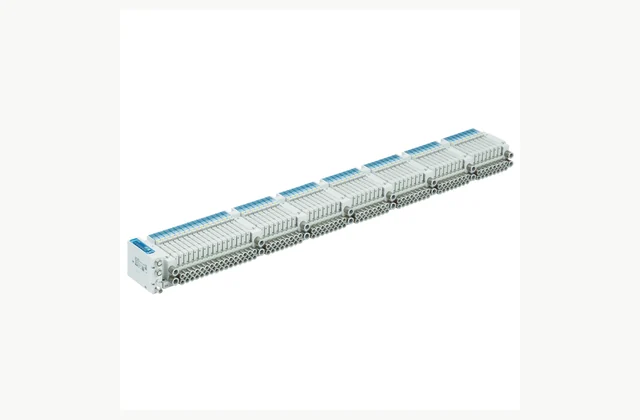
Shown as a configuration reference. Availability and the equipment offered for your project are confirmed separately.
Create a station-by-station valve schedule
List each actuator and the required valve symbol, spool state, flow and coil arrangement. Reserve spare stations intentionally. Similar manifold bodies can hold valves with different functions, so a total station count is insufficient to establish how the assembled island will operate.
Separate pressure and exhaust zones
Some machine functions need different supply pressure or independent exhaust treatment. Define these circuits and the required isolation accessories. Shared passages can couple otherwise separate motions, so confirm separators, supply blocks and exhaust routing in the actual manifold drawing rather than a generic family image.
Check simultaneous flow and pressure drop
Provide the motions that occur together, cylinder sizes and desired timing. Common supply and exhaust capacity can limit a valve island even when individual valves seem adequate. Assess pressure at the active stations under combined demand, including long tubing and muffler restrictions.
Match fieldbus and electrical loading
Specify network protocol, controller, addressing, power supplies and output behavior. Check station and coil limits for the exact communication unit and accessories. A familiar connector does not guarantee protocol compatibility, and software configuration should identify the delivered island's actual station order.
Define diagnostics and safe recovery
Decide which faults the host controller must detect and how the machine responds to network or supply loss. Standard manifold diagnostics do not establish a validated safety stop. Document the valve states, retained pressure and restart sequence in the machine's engineered pneumatic and control design.
Keep configuration and replacements controlled
Obtain the assembled manifold code, wiring, pneumatic drawing and replacement valve identifiers. Record firmware and configuration files where relevant. Replacing a similar-looking valve or moving a station can change the machine behavior, so maintenance needs a controlled map and a verification procedure.
Compare a complete pneumatic valve manifold scope
| Decision | Information to compare |
|---|---|
| Create a station-by-station valve schedule | Valve station schedule, symbols, coil count and reserved expansion |
| Separate pressure and exhaust zones | Pressure zones, separators, supply blocks, exhaust zones and residual air |
| Check simultaneous flow and pressure drop | Simultaneous actuators, common flow, pressure drop and tubing lengths |
| Match fieldbus and electrical loading | Fieldbus, controller version, addressing, coil power and station limits |
| Define diagnostics and safe recovery | Diagnostic signals, communication loss, valve defaults and restart strategy |
| Keep configuration and replacements controlled | Assembled code, station map, firmware/configuration and replacement parts |
Plan installation and access
Support the island securely, allow replacement and connector access and route tubing by station identification. Confirm supply, exhaust and protective grounding with the delivered drawing. Label pressure zones and provide a safe way to isolate and discharge each affected circuit before maintenance.
Agree acceptance evidence before ordering
Exercise all stations individually and in the planned simultaneous groups. Check pressure drop, travel timing, leaks, diagnostics and communication restart. Verify the delivered physical station order against the controller map and demonstrate controlled valve replacement, retaining the final assembly code and configuration backup.
Define OEM/ODM engineering boundaries
OEM station layouts, connectors and approved pressure-zone combinations can be assessed. ODM valve passages, electronics or safety behavior require engineering and validation. The reference island photo illustrates a family and is not proof that a pictured station count or fieldbus module is included in a quotation.
What should your pneumatic valve manifold RFQ include?
- Valve station schedule, symbols, coil count and reserved expansion
- Pressure zones, separators, supply blocks, exhaust zones and residual air
- Simultaneous actuators, common flow, pressure drop and tubing lengths
- Fieldbus, controller version, addressing, coil power and station limits
- Diagnostic signals, communication loss, valve defaults and restart strategy
- Assembled code, station map, firmware/configuration and replacement parts
- Destination, working environment, access and delivery constraints
- Installation responsibility, utilities and connection drawings
- Acceptance samples, documented test method, operator training and maintenance scope
- OEM/ODM changes requested: identification, tooling, interfaces or new design; engineering feasibility to be confirmed
Need OEM / ODM customization?
Submit branding, packaging, configuration or engineering requirements for this equipment. Include the target market, initial and annual quantities, required changes and acceptance criteria.
Customization feasibility, permitted branding, development responsibilities, minimum quantity, cost and lead time are reviewed for the proposed supplier and configuration before a quotation is confirmed.
Frequently asked questions
How do I create a station-by-station valve schedule?
List each actuator and the required valve symbol, spool state, flow and coil arrangement. Reserve spare stations intentionally. Similar manifold bodies can hold valves with different functions, so a total station count is insufficient to establish how the assembled island will operate.
How do I separate pressure and exhaust zones?
Some machine functions need different supply pressure or independent exhaust treatment. Define these circuits and the required isolation accessories. Shared passages can couple otherwise separate motions, so confirm separators, supply blocks and exhaust routing in the actual manifold drawing rather than a generic family image.
How do I check simultaneous flow and pressure drop?
Provide the motions that occur together, cylinder sizes and desired timing. Common supply and exhaust capacity can limit a valve island even when individual valves seem adequate. Assess pressure at the active stations under combined demand, including long tubing and muffler restrictions.
How do I match fieldbus and electrical loading?
Specify network protocol, controller, addressing, power supplies and output behavior. Check station and coil limits for the exact communication unit and accessories. A familiar connector does not guarantee protocol compatibility, and software configuration should identify the delivered island's actual station order.
How do I define diagnostics and safe recovery?
Decide which faults the host controller must detect and how the machine responds to network or supply loss. Standard manifold diagnostics do not establish a validated safety stop. Document the valve states, retained pressure and restart sequence in the machine's engineered pneumatic and control design.
How do I keep configuration and replacements controlled?
Obtain the assembled manifold code, wiring, pneumatic drawing and replacement valve identifiers. Record firmware and configuration files where relevant. Replacing a similar-looking valve or moving a station can change the machine behavior, so maintenance needs a controlled map and a verification procedure.
Reference information
- SMC JSY3000-L official product reference
- SMC pneumatic valve manifold official family or technical reference
Reference data and images explain equipment configurations. IndustryApex engineers confirm the offered model, specification and commercial scope in your project quotation.