
Plate dishing and flanging system should be selected using dished-head geometry, forming sequence and plate-handling responsibility, with the receiving site and upstream or downstream equipment included in the discussion. Compare the proposed configuration, stated assumptions and a realistic acceptance trial together. Ask each supplier to identify exclusions, maintenance responsibilities and unresolved application questions. Define OEM branding separately from ODM integration changes so an altered machine is assessed against the same documented production requirement.
Compare plate dishing and flanging system proposals around dished-head geometry, forming sequence and plate-handling responsibility. Define the process boundary, supporting equipment and acceptance evidence before choosing a configuration. Send the same application details to each bidder and include project-specific OEM or ODM requirements in the initial inquiry.
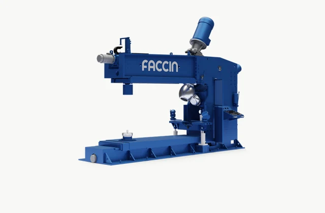
Shown as a configuration reference. Availability and the equipment offered for your project are confirmed separately.
Define the complete head geometry and material
Provide head diameter, crown and knuckle geometry, straight flange and material grade with starting and required finished thickness. State whether heads are for a pressure vessel or another use and identify the responsible design requirements. A press-force or maximum-diameter headline does not establish the accepted head shape, thinning or documentation for every material and forming route.
Supply the actual drawing rather than only a familiar head-shape name. Include welds in the starting blank where relevant and clarify any heat-treatment assumptions. Have the responsible vessel or product engineer define acceptance before a supplier proposes a dishing and flanging combination.
Review dishing and flanging as separate linked operations
A production system may use a dishing press with handling equipment followed by a separate flanging machine. Other arrangements depend on the head and production requirements. Ask the supplier to map the complete route from flat blank to accepted head, including manipulation, trimming and intermediate work. A flanging machine image should not be interpreted as proof that a complete dishing line is included.
The Faccin BF reference illustrates the flanging stage; its PPM/MA documentation provides a dishing-press and manipulator reference. Confirm the actual equipment combination and boundaries. Keep each reference model’s role explicit rather than assigning an invented single model to the whole custom system.
Compare tooling, manipulation and thickness effects
Match dies, forming rolls, supports and manipulators to the actual geometry and material. Ask how the proposed route controls crown shape, knuckle form and thickness reduction. Compare the starting blank assumptions and any intermediate operations. A machine capable of moving a large blank may still need another tool or process step to obtain the specified head without unacceptable deformation or surface damage.
Discuss the difficult diameter and thickness combinations separately. Do not apply a capacity based on ordinary steel to another strength or material without review. Request a clear response identifying which head families are established applications and which require further forming trials or engineering.
| Decision | Requirement to state | Evidence to request |
|---|---|---|
| Head | Crown, knuckle, flange and thickness | Complete engineering drawing |
| Route | Dishing, transfer, flanging and trimming | Operation-by-operation system boundary |
| Tools | Dies, rolls and manipulation | Material-specific forming response |
| Site | Heavy blank and head movements | Allocated layout and civil requirements |
| Acceptance | Geometry, surface and thickness | Traceable responsible inspection plan |
Plan heavy-blank movement and installation
Provide blank dimensions and handling weight, lifting resources, floor arrangement and available service routes. Allocate foundations, manipulation, transfer between operations, hydraulics and electrical service to the responsible parties. Show how a partially formed head is supported and moved. The protected working area and handling envelope can extend far beyond a press or flanger’s base footprint.
Include space to change tooling and remove large service components. If hot forming is proposed, have responsible specialists define the additional process and handling requirements. Keep heating, cooling and subsequent inspection boundaries explicit rather than treating them as incidental shop tasks outside a forming quotation.
Inspect the head against its engineering drawing
Use agreed material and starting blanks to produce representative heads, then inspect geometry, flange dimensions, surface condition and thickness distribution as required by the responsible design. Record tooling, sequence and intermediate operations. Where vessel-specific inspections or documentation are needed, assign them to qualified responsible parties. A visually smooth head does not independently establish conformity for pressure service or a complete manufacturing route.
Retain measurement locations and material traceability with the report. Observe transfers and normal tooling changes as well as forming movement. If full-size trials are deferred, list the remaining application evidence clearly instead of describing a smaller demonstration as complete validation of every required head.
Define customized head-forming systems under ODM
OEM requests can cover labels and documents while preserving original machine identity. ODM work may involve tools, manipulators, controls, transfers or a complete head-forming line. Require engineering review of loads, geometry, material behavior and protective functions. Define ownership of tooling and drawings plus project-specific acceptance; a reference manufacturer’s equipment does not establish relabeling rights or automatic compliance of the finished head.
Request service identifiers for forming tools, rolls and handling components. Clarify who supports faults spanning press, manipulator and flanger. Keep the product engineer’s acceptance requirements linked to the actual delivered line and any future change in material or head geometry.
The pictured manufacturer equipment and linked documents are technical configuration references. They do not imply authorized representation, stock availability, equivalent performance from another supplier or permission to relabel the pictured brand. Confirm the proposed equipment and commercial scope for the specific project.
What should your plate dishing and flanging system RFQ include?
- Head drawings with crown, knuckle and flange geometry
- Material grades, blank size and starting/finished thickness
- Intended service and responsible design requirements
- Welded blanks, heat treatment and forming-route assumptions
- Dishing press, flanger, dies and manipulator scope
- Geometry, thinning, surface and documentation acceptance
- Blank/head handling loads and transfer/lifting resources
- Foundations, hydraulics, power and tooling service access
- Representative head trials and qualified inspection responsibilities
- OEM documents or ODM tooling, transfer and control integration
Need OEM / ODM customization?
Submit branding, packaging, configuration or engineering requirements for this equipment. Include the target market, initial and annual quantities, required changes and acceptance criteria.
Customization feasibility, permitted branding, development responsibilities, minimum quantity, cost and lead time are reviewed for the proposed supplier and configuration before a quotation is confirmed.
Frequently asked questions
What should I specify for plate dishing and flanging equipment?
Provide head diameter, crown and knuckle geometry, straight flange and material grade with starting and required finished thickness. State whether heads are for a pressure vessel or another use and identify the responsible design requirements. A press-force or maximum-diameter headline does not establish the accepted head shape, thinning or documentation for every material and forming route.
Does one machine perform both dishing and flanging?
A production system may use a dishing press with handling equipment followed by a separate flanging machine. Other arrangements depend on the head and production requirements. Ask the supplier to map the complete route from flat blank to accepted head, including manipulation, trimming and intermediate work. A flanging machine image should not be interpreted as proof that a complete dishing line is included.
What should dished-head equipment quotations compare?
Match dies, forming rolls, supports and manipulators to the actual geometry and material. Ask how the proposed route controls crown shape, knuckle form and thickness reduction. Compare the starting blank assumptions and any intermediate operations. A machine capable of moving a large blank may still need another tool or process step to obtain the specified head without unacceptable deformation or surface damage.
What installation information is needed for a head-forming system?
Provide blank dimensions and handling weight, lifting resources, floor arrangement and available service routes. Allocate foundations, manipulation, transfer between operations, hydraulics and electrical service to the responsible parties. Show how a partially formed head is supported and moved. The protected working area and handling envelope can extend far beyond a press or flanger's base footprint.
How should dishing and flanging acceptance be handled?
Use agreed material and starting blanks to produce representative heads, then inspect geometry, flange dimensions, surface condition and thickness distribution as required by the responsible design. Record tooling, sequence and intermediate operations. Where vessel-specific inspections or documentation are needed, assign them to qualified responsible parties. A visually smooth head does not independently establish conformity for pressure service or a complete manufacturing route.
Can plate dishing and flanging equipment support OEM or ODM?
OEM requests can cover labels and documents while preserving original machine identity. ODM work may involve tools, manipulators, controls, transfers or a complete head-forming line. Require engineering review of loads, geometry, material behavior and protective functions. Define ownership of tooling and drawings plus project-specific acceptance; a reference manufacturer's equipment does not establish relabeling rights or automatic compliance of the finished head.
Reference information
- Faccin: BF flanging machine (dished-head forming system reference) official product reference
- Faccin official supporting product documentation
Reference data and images explain equipment configurations. IndustryApex engineers confirm the offered model, specification and commercial scope in your project quotation.