
A mill-turn system combines turning with driven-tool milling and drilling to reduce handling between operations. Selection should prove completion of the intended component in the available clamping positions rather than count axes alone. Choose the configuration by operation consolidation and datums and collision envelope and tool capacity. Machine a complete representative part and measure cross-operation relationships, surface quality and burrs. Include tool change, transfer, program restart and the proposed method of verifying the combined cycle. OEM/ODM requirements are reviewed against the intended process, site interfaces and acceptance evidence; the reference image identifies a product family and does not establish supply availability or an authorized brand relationship.
A mill-turn system combines turning with driven-tool milling and drilling to reduce handling between operations. Selection should prove completion of the intended component in the available clamping positions rather than count axes alone. Combines driven milling and turning in one workpiece strategy; assess access and transfer operations.
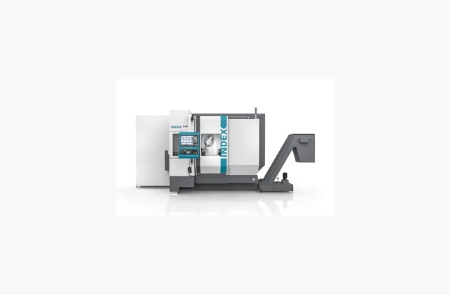
Shown as a configuration reference. Availability and the equipment offered for your project are confirmed separately.
What is the application scope for mill-turn machining system?
A mill-turn system combines turning with driven-tool milling and drilling to reduce handling between operations. Selection should prove completion of the intended component in the available clamping positions rather than count axes alone.
Combines driven milling and turning in one workpiece strategy; assess access and transfer operations. Consolidating operations can reduce datum changes, but only when tools can reach the necessary features in the proposed clamping sequence. Check collision clearance with the real fixture and longest tools. Simultaneous motions and subspindle transfer also need a validated program and postprocessor. Compare the complete inspected component and any remaining secondary work rather than adding theoretical time savings from unrelated machine operations.
How should operation consolidation and datums be specified?
Supply the complete drawing and current route, including features normally made in secondary setups. Determine which faces remain accessible and where subspindle transfer or reclamping changes the datum chain.
The RFQ should make operation consolidation and datums a separate review item. Describe the expected variation, not only the easiest operating case, and ask the bidder to identify restrictions that affect the intended production mix.
What configuration evidence should be compared?
Compare milling spindle orientation, turret or magazine space, steady rests and workpiece support. Long tools and large fixtures may restrict simultaneous motion even when individual axis travels appear sufficient.
| Decision | Evidence to compare | Procurement consequence |
|---|---|---|
| Operation consolidation and datums | Supply the complete drawing and current route, including features normally made in secondary setups. Determine which faces remain accessible and where subspindle transfer or reclamping changes the datum chain. | Defines the input and work envelope to be included in the offer. |
| Collision envelope and tool capacity | Compare milling spindle orientation, turret or magazine space, steady rests and workpiece support. Long tools and large fixtures may restrict simultaneous motion even when individual axis travels appear sufficient. | Determines configuration, supporting equipment and exclusions. |
| Production acceptance | Machine a complete representative part and measure cross-operation relationships, surface quality and burrs. Include tool change, transfer, program restart and the proposed method of verifying the combined cycle. | Establishes the agreed demonstration and inspection records. |
What must be prepared for installation?
Provide bar or blank loading, chip management, coolant treatment and tool-presetting space. Confirm access for servicing both turning and milling assemblies.
Keep the proven CAM/postprocessor version, machine program, tool data and transfer sequence together. The receiving team should demonstrate recovery from an interrupted combined cycle and repeat cross-operation measurements after kinematic calibration or a tooling-layout change.
How should production acceptance be demonstrated?
Machine a complete representative part and measure cross-operation relationships, surface quality and burrs. Include tool change, transfer, program restart and the proposed method of verifying the combined cycle.
Define acceptable results before the trial and retain the test records. Include a realistic restart and a representative changeover; investigate rejected output rather than reporting only the best part of a demonstration.
Which service provisions protect repeatability?
Maintain kinematic calibration, tool data, spindle condition and program backups. Establish which support team resolves problems involving both CAM output and machine-axis coordination.
Obtain a preventive schedule, spare-parts list and escalation contact before shipment. Confirm what can be diagnosed remotely, what requires trained local personnel and how replacement components will be identified after revisions.
What can be customized through OEM or ODM?
OEM loading and probing can be integrated; ODM part processes require collision simulation, postprocessor verification and acceptance of the complete finished component.
Submit the proposed changes with the mill-turn machining system duty and acceptance plan. Separate a purchased option from new engineering, and agree drawings, validation responsibility, documentation and spare-part support before design release. The manufacturer example is a technical reference only; customization does not imply permission to copy protected designs or use a brand.
What should your mill-turn machining system RFQ include?
- Mill-turn machining system application and required process result
- Operation consolidation and datums: Supply the complete drawing and current route, including features normally made in secondary setups. Determine which faces remain accessible and where subspindle transfer or reclamping changes the datum chain.
- Collision envelope and tool capacity: Compare milling spindle orientation, turret or magazine space, steady rests and workpiece support. Long tools and large fixtures may restrict simultaneous motion even when individual axis travels appear sufficient.
- Representative input variation and difficult production cases
- Required acceptance evidence: Machine a complete representative part and measure cross-operation relationships, surface quality and burrs. Include tool change, transfer, program restart and the proposed method of verifying the combined cycle.
- Site and utility scope: Provide bar or blank loading, chip management, coolant treatment and tool-presetting space. Confirm access for servicing both turning and milling assemblies.
- Service provision: Maintain kinematic calibration, tool data, spindle condition and program backups. Establish which support team resolves problems involving both CAM output and machine-axis coordination.
- OEM/ODM engineering scope: OEM loading and probing can be integrated; ODM part processes require collision simulation, postprocessor verification and acceptance of the complete finished component.
- Upstream preparation and downstream handling interfaces
- Destination country and applicable installation requirements
- Production schedule, changeover mix and operator availability
- Drawings, samples, inspection method and rejected-output criteria
Need OEM / ODM customization?
Submit branding, packaging, configuration or engineering requirements for this equipment. Include the target market, initial and annual quantities, required changes and acceptance criteria.
Customization feasibility, permitted branding, development responsibilities, minimum quantity, cost and lead time are reviewed for the proposed supplier and configuration before a quotation is confirmed.
Frequently asked questions
What defines the application boundary for mill-turn machining system?
A mill-turn system combines turning with driven-tool milling and drilling to reduce handling between operations. Selection should prove completion of the intended component in the available clamping positions rather than count axes alone. Combines driven milling and turning in one workpiece strategy; assess access and transfer operations. Define the intended production result before comparing nominal ratings, and ask for evidence using the actual input conditions.
What should the mill-turn machining system RFQ state about operation consolidation and datums?
Supply the complete drawing and current route, including features normally made in secondary setups. Determine which faces remain accessible and where subspindle transfer or reclamping changes the datum chain. Send the representative inputs and the difficult cases together, then require the supplier to state any restrictions or preparation steps needed to repeat the proposed result.
How should collision envelope and tool capacity be checked?
Compare milling spindle orientation, turret or magazine space, steady rests and workpiece support. Long tools and large fixtures may restrict simultaneous motion even when individual axis travels appear sufficient. Ask the bidder to document the selected arrangement and exclusions against the real duty. Confirm which supporting components and setup work are included in the commercial scope.
What acceptance test is appropriate for mill-turn machining system?
Machine a complete representative part and measure cross-operation relationships, surface quality and burrs. Include tool change, transfer, program restart and the proposed method of verifying the combined cycle. Agree the sampling method and rejection criteria before the trial, and keep configuration and inspection records for the later site-acceptance comparison.
What installation and service details should be confirmed?
Provide bar or blank loading, chip management, coolant treatment and tool-presetting space. Confirm access for servicing both turning and milling assemblies. Maintain kinematic calibration, tool data, spindle condition and program backups. Establish which support team resolves problems involving both CAM output and machine-axis coordination. Allocate local preparations and specialist support to named parties before shipment so commissioning and subsequent maintenance have a clear owner.
Can mill-turn machining system configurations be customized through OEM or ODM?
OEM loading and probing can be integrated; ODM part processes require collision simulation, postprocessor verification and acceptance of the complete finished component. Supply drawings and operating conditions for feasibility review. Engineering changes require agreed validation and documentation; a reference brand image does not establish an authorized supply or manufacturing relationship.
Reference information
- Turn-Mill Center INDEX G160 | INDEX Group
- Turn-mill centers - INDEX Corporation
Reference data and images explain equipment configurations. IndustryApex engineers confirm the offered model, specification and commercial scope in your project quotation.