
MIG/MAG welding feeds consumable wire into an arc protected by shielding gas. The gas, transfer mode and procedure must match the joint and material rather than the power source label alone. Choose the configuration by joint and wire system and transfer mode and package boundary. Weld representative joints and inspect bead profile, fusion, porosity and distortion using the agreed procedure. Include starts, stops and a consumable change. OEM/ODM requirements are reviewed against the intended process, site interfaces and acceptance evidence; the reference image identifies a product family and does not establish supply availability or an authorized brand relationship.
MIG/MAG welding feeds consumable wire into an arc protected by shielding gas. The gas, transfer mode and procedure must match the joint and material rather than the power source label alone. Wire-fed arc joining with shielding gas; procedure trials must match material and joint design.
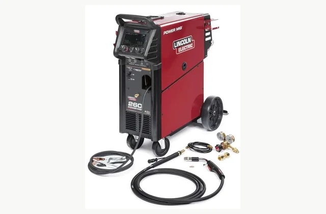
Shown as a configuration reference. Availability and the equipment offered for your project are confirmed separately.
What is the application scope for mig/mag welding system?
MIG/MAG welding feeds consumable wire into an arc protected by shielding gas. The gas, transfer mode and procedure must match the joint and material rather than the power source label alone.
Wire-fed arc joining with shielding gas; procedure trials must match material and joint design. A high peak current does not establish usable duty cycle, joint quality or suitability for a specific alloy.
How should joint and wire system be specified?
State base material, thickness range, joint preparation, welding position, filler and gas. Include wire spool format, feed distance and duty under the actual production schedule.
The RFQ should make joint and wire system a separate review item. Describe the expected variation, not only the easiest operating case, and ask the bidder to identify restrictions that affect the intended production mix.
What configuration evidence should be compared?
Compare short-circuit, pulsed or other supported modes using relevant joints. Quote wire feeder, torch cooling, return cables, gas regulation and extraction separately from optional automation.
Start with the bottleneck and the product-quality requirement. Map how material or energy enters and leaves the process, then check whether a proposed configuration changes staffing, auxiliary equipment or the validation work required on site.
| Decision | Evidence to compare | Procurement consequence |
|---|---|---|
| Joint and wire system | State base material, thickness range, joint preparation, welding position, filler and gas. Include wire spool format, feed distance and duty under the actual production schedule. | Defines the input and work envelope to be included in the offer. |
| Transfer mode and package boundary | Compare short-circuit, pulsed or other supported modes using relevant joints. Quote wire feeder, torch cooling, return cables, gas regulation and extraction separately from optional automation. | Determines configuration, supporting equipment and exclusions. |
| Production acceptance | Weld representative joints and inspect bead profile, fusion, porosity and distortion using the agreed procedure. Include starts, stops and a consumable change. | Establishes the agreed demonstration and inspection records. |
What must be prepared for installation?
Provide electrical supply, shielding gas, return-current routing, fume extraction and protected cylinder storage.
Turn the layout into a practical installation checklist. Include support services, safe access, operator positions and the means of isolating stored energy, with responsibilities agreed between the supplier and receiving facility.
How should production acceptance be demonstrated?
Weld representative joints and inspect bead profile, fusion, porosity and distortion using the agreed procedure. Include starts, stops and a consumable change.
Inspect the result over a meaningful operating cycle rather than accepting a brief unloaded demonstration. Record setup effort and adjustments alongside output so the buyer can assess the staffing and skill needed to reproduce it.
Which service provisions protect repeatability?
Maintain contact tips, liners, drive rolls, gas seals and calibration; preserve approved procedures and parameter records.
Keep maintenance traceability to the serial number and installed options. Agree the route for technical assistance and the minimum local skills needed, including the evidence to collect before requesting remote troubleshooting.
What can be customized through OEM or ODM?
OEM torches, interfaces and fixtures may be configured; ODM automated joining needs procedure development and complete cell validation.
Submit the proposed changes with the mig/mag welding system duty and acceptance plan. Separate a purchased option from new engineering, and agree drawings, validation responsibility, documentation and spare-part support before design release. The manufacturer example is a technical reference only; customization does not imply permission to copy protected designs or use a brand.
Request an itemized offer that identifies tooling or auxiliaries, freight assumptions, commissioning, operator training and recurring consumables. Agree who supplies trial inputs and inspection instruments, and resolve deviations before comparing the complete project cost.
What should your mig/mag welding system RFQ include?
- MIG/MAG welding system application and required process result
- Joint and wire system: State base material, thickness range, joint preparation, welding position, filler and gas. Include wire spool format, feed distance and duty under the actual production schedule.
- Transfer mode and package boundary: Compare short-circuit, pulsed or other supported modes using relevant joints. Quote wire feeder, torch cooling, return cables, gas regulation and extraction separately from optional automation.
- Representative input variation and difficult production cases
- Required acceptance evidence: Weld representative joints and inspect bead profile, fusion, porosity and distortion using the agreed procedure. Include starts, stops and a consumable change.
- Site and utility scope: Provide electrical supply, shielding gas, return-current routing, fume extraction and protected cylinder storage.
- Service provision: Maintain contact tips, liners, drive rolls, gas seals and calibration; preserve approved procedures and parameter records.
- OEM/ODM engineering scope: OEM torches, interfaces and fixtures may be configured; ODM automated joining needs procedure development and complete cell validation.
- Upstream preparation and downstream handling interfaces
- Destination country and applicable installation requirements
- Production schedule, changeover mix and operator availability
- Drawings, samples, inspection method and rejected-output criteria
Need OEM / ODM customization?
Submit branding, packaging, configuration or engineering requirements for this equipment. Include the target market, initial and annual quantities, required changes and acceptance criteria.
Customization feasibility, permitted branding, development responsibilities, minimum quantity, cost and lead time are reviewed for the proposed supplier and configuration before a quotation is confirmed.
Frequently asked questions
What defines the application boundary for mig/mag welding system?
MIG/MAG welding feeds consumable wire into an arc protected by shielding gas. The gas, transfer mode and procedure must match the joint and material rather than the power source label alone. Wire-fed arc joining with shielding gas; procedure trials must match material and joint design. Define the intended production result before comparing nominal ratings, and ask for evidence using the actual input conditions.
What should the mig/mag welding system RFQ state about joint and wire system?
State base material, thickness range, joint preparation, welding position, filler and gas. Include wire spool format, feed distance and duty under the actual production schedule. Send the representative inputs and the difficult cases together, then require the supplier to state any restrictions or preparation steps needed to repeat the proposed result.
How should transfer mode and package boundary be checked?
Compare short-circuit, pulsed or other supported modes using relevant joints. Quote wire feeder, torch cooling, return cables, gas regulation and extraction separately from optional automation. Ask the bidder to document the selected arrangement and exclusions against the real duty. Confirm which supporting components and setup work are included in the commercial scope.
What acceptance test is appropriate for mig/mag welding system?
Weld representative joints and inspect bead profile, fusion, porosity and distortion using the agreed procedure. Include starts, stops and a consumable change. Agree the sampling method and rejection criteria before the trial, and keep configuration and inspection records for the later site-acceptance comparison.
What installation and service details should be confirmed?
Provide electrical supply, shielding gas, return-current routing, fume extraction and protected cylinder storage. Maintain contact tips, liners, drive rolls, gas seals and calibration; preserve approved procedures and parameter records. Allocate local preparations and specialist support to named parties before shipment so commissioning and subsequent maintenance have a clear owner.
Can mig/mag welding system configurations be customized through OEM or ODM?
OEM torches, interfaces and fixtures may be configured; ODM automated joining needs procedure development and complete cell validation. Supply drawings and operating conditions for feasibility review. Engineering changes require agreed validation and documentation; a reference brand image does not establish an authorized supply or manufacturing relationship.
Reference information
- POWER MIG® 260
- Calibration system 2.0
Reference data and images explain equipment configurations. IndustryApex engineers confirm the offered model, specification and commercial scope in your project quotation.