
CNC metal spinning machine should be selected using rotational part geometry, material condition and controlled spinning paths, with the receiving site and upstream or downstream equipment included in the discussion. Compare the proposed configuration, stated assumptions and a realistic acceptance trial together. Ask each supplier to identify exclusions, maintenance responsibilities and unresolved application questions. Define OEM branding separately from ODM integration changes so an altered machine is assessed against the same documented production requirement.
Compare cnc metal spinning machine proposals around rotational part geometry, material condition and controlled spinning paths. Define the process boundary, supporting equipment and acceptance evidence before choosing a configuration. Send the same application details to each bidder and include project-specific OEM or ODM requirements in the initial inquiry.
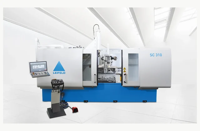
Shown as a configuration reference. Availability and the equipment offered for your project are confirmed separately.
Define the part and its starting blank
Provide the finished rotational part drawing, material grade, blank or preform dimensions and required wall distribution. State whether the process is conventional spinning, shear forming or another intended forming route for review. A maximum blank diameter does not establish that the component can be made without unacceptable thinning, wrinkles or cracks. Include trim allowances and any intermediate heat treatment or annealing assumptions.
Mark the critical surfaces, concentric features and final assembly references. Explain whether the part is a reflector, duct component, cover or another geometry. Similar outside shapes can have very different requirements for wall control and tooling support.
Review mandrels, rollers and tailstock access
The mandrel, roller geometry, support and tailstock arrangement determine how the blank is held and formed. Ask the supplier to review the complete tool path and part-removal method for your component. A machine’s nominal force and travel do not prove access around an undercut or the ability to remove a finished shape from a one-piece mandrel without additional tooling.
Compare tool preparation and changes across the intended part family. Identify whether a split mandrel or special support is proposed. Keep custom tool ownership and maintenance information in the offer because an accepted spinning process can depend heavily on details beyond the machine frame.
Distinguish programmed motion from a proven forming process
CNC provides controlled motion, but successful spinning still depends on material, blank preparation, tooling, lubrication and the forming path. Ask how the supplier develops and transfers the process for a new part. Compare the resulting geometry and wall condition on real material. A stored program or a playback demonstration is not independent evidence that another alloy or blank thickness will form successfully.
The LEIFELD SC reference illustrates a spinning-center configuration. Confirm the offered control, axes and tooling rather than inferring identical capability from another machine’s program. Clarify how qualified operators revise paths and how process recipes are backed up and kept traceable.
| Decision | Requirement to state | Evidence to request |
|---|---|---|
| Part | Contour, wall and material condition | Finished drawing and starting blank |
| Tools | Mandrel, rollers and removal access | Application-specific tooling plan |
| Process | Path, lubrication and intermediate work | Traceable forming development trial |
| Cell | Loading, trimming and unloading | Complete protected production boundary |
| Result | Geometry, surface and wall distribution | Inspected production-material parts |
Plan blank loading and finished-part removal
Allocate blank presentation, tooling handling, lubrication, trim handling and the method for removing the formed part. Review power, installation loads and service access with the manufacturer. Include the largest blank’s movement and the tool-change route. If automatic loading is proposed, confirm how blank identity, orientation and unusual shapes are handled within the complete protected cell boundary.
Ask whether trimming or secondary forming is included or performed elsewhere. A forming-only machine should not be compared with a cell that delivers a trimmed component without identifying that difference. Keep scrap collection and any lubricant management visible in the production layout.
Inspect geometry and wall condition after forming
Form representative parts using the agreed production material and inspect contour, dimensions, concentricity, surface condition and wall distribution as required by the drawing. Record tooling, lubrication, program and any intermediate operations. Include normal setup and unloading in the observed sequence. A visually attractive shell does not establish that critical wall regions or mating features meet the accepted engineering requirement.
Have the receiving operator demonstrate program selection and a routine tool setup after training. Retain material identification and measurement locations with the report. If process development remains unfinished, state the open trials clearly rather than describing an unproven part family as production-ready.
Define custom forming work under OEM/ODM
OEM requests may include approved labels, manuals and a documented tooling package. ODM work can involve mandrels, roller arrangements, controls, loading or an integrated forming sequence. Require application trials and engineering review of the changed tooling and cell. Define program and drawing ownership plus acceptance of the actual component; a reference manufacturer’s image does not establish relabeling permission or equivalence of another spinning machine.
Request service identification for rollers, supports and control components on the delivered configuration. Clarify who supports new-part process development after handover. Keep the boundary between machine maintenance and application engineering explicit so future shapes are reviewed with the right technical evidence.
The pictured manufacturer equipment and linked documents are technical configuration references. They do not imply authorized representation, stock availability, equivalent performance from another supplier or permission to relabel the pictured brand. Confirm the proposed equipment and commercial scope for the specific project.
What should your cnc metal spinning machine RFQ include?
- Finished rotational part drawings and datums
- Material grade, blank/preform size and condition
- Wall distribution, thinning and contour acceptance
- Spinning/shear-forming route and intermediate operations
- Mandrel, roller, tailstock and part-removal review
- Program development, editing rights and backups
- Blank loading, lubrication, trimming and scrap scope
- Installation, power, tooling handling and service access
- Actual-material forming trial and measurement locations
- OEM tooling or ODM forming path, controls and cell review
Need OEM / ODM customization?
Submit branding, packaging, configuration or engineering requirements for this equipment. Include the target market, initial and annual quantities, required changes and acceptance criteria.
Customization feasibility, permitted branding, development responsibilities, minimum quantity, cost and lead time are reviewed for the proposed supplier and configuration before a quotation is confirmed.
Frequently asked questions
What should I specify for a CNC metal spinning machine?
Provide the finished rotational part drawing, material grade, blank or preform dimensions and required wall distribution. State whether the process is conventional spinning, shear forming or another intended forming route for review. A maximum blank diameter does not establish that the component can be made without unacceptable thinning, wrinkles or cracks. Include trim allowances and any intermediate heat treatment or annealing assumptions.
How does tooling affect CNC spinning machine selection?
The mandrel, roller geometry, support and tailstock arrangement determine how the blank is held and formed. Ask the supplier to review the complete tool path and part-removal method for your component. A machine's nominal force and travel do not prove access around an undercut or the ability to remove a finished shape from a one-piece mandrel without additional tooling.
Does CNC control guarantee a finished spun part?
CNC provides controlled motion, but successful spinning still depends on material, blank preparation, tooling, lubrication and the forming path. Ask how the supplier develops and transfers the process for a new part. Compare the resulting geometry and wall condition on real material. A stored program or a playback demonstration is not independent evidence that another alloy or blank thickness will form successfully.
What equipment belongs around a CNC spinning machine?
Allocate blank presentation, tooling handling, lubrication, trim handling and the method for removing the formed part. Review power, installation loads and service access with the manufacturer. Include the largest blank's movement and the tool-change route. If automatic loading is proposed, confirm how blank identity, orientation and unusual shapes are handled within the complete protected cell boundary.
How should CNC metal spinning acceptance be tested?
Form representative parts using the agreed production material and inspect contour, dimensions, concentricity, surface condition and wall distribution as required by the drawing. Record tooling, lubrication, program and any intermediate operations. Include normal setup and unloading in the observed sequence. A visually attractive shell does not establish that critical wall regions or mating features meet the accepted engineering requirement.
Can a CNC spinning machine support OEM or ODM?
OEM requests may include approved labels, manuals and a documented tooling package. ODM work can involve mandrels, roller arrangements, controls, loading or an integrated forming sequence. Require application trials and engineering review of the changed tooling and cell. Define program and drawing ownership plus acceptance of the actual component; a reference manufacturer's image does not establish relabeling permission or equivalence of another spinning machine.
Reference information
- LEIFELD: SC 310 spinning center official product reference
- LEIFELD official supporting product documentation
Reference data and images explain equipment configurations. IndustryApex engineers confirm the offered model, specification and commercial scope in your project quotation.