
Choose between combined or dedicated C and Z purlin tooling by reviewing your profile family, material gauge range, and changeover frequency. Request a profile-by-profile capability table, gauge adjustment method, and realistic setup demonstration with the exact coil specifications you will run.
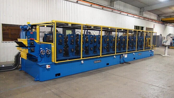
Shown as a configuration reference. Availability and the equipment offered for your project are confirmed separately.
Configuration choice: combined or dedicated tooling
C and Z purlin roll forming machines differ in how they handle profile changes. Some lines form both sections in a single roll space using repositionable or double-faced tooling, eliminating the need to exchange complete tool sets between C and Z runs [S1]. Other configurations use separate dedicated tooling for each profile family, requiring a complete toolchange or parallel forming heads. Choose the approach that fits your actual job mix and the economic value of faster changeovers.
Review whether the proposed line handles gauge adjustment automatically or manually. Automatic systems reduce setup labor and variation between operators; manual adjustment requires documented procedures and skilled setup personnel. Ask how the line transitions between minimum and maximum material thickness within your specified range, and whether intermediate gauges need additional spacers or tool changes.
Profile family and tooling scope
Define every profile size, height, flange width, and lip configuration you intend to produce. A single nominal section width does not establish the ability to run a family of sizes. Some machines adjust within a defined range using telescoping arbors or lateral shifts; others need exchanged tooling cartridges or separate forming stands for each profile. Request a written profile-by-profile capability table that states which sections are included in the base configuration, which require optional tooling, and which fall outside the machine’s adjustment range.
Identify coil width, material grade, yield strength, coating type, and thickness ranges together. Heavier gauge material and high-strength steel increase forming forces and may limit the practical profile range or production speed. Coated or pre-painted surfaces require roll designs that minimize scuffing and surface contact. Submit representative coil specifications and finished profile drawings with tolerances so the supplier can confirm that the proposed tooling and adjustment mechanisms suit your actual operating conditions.
Buyer input worksheet
| Buyer input | Purpose | Rejection condition |
|---|---|---|
| Complete profile family drawings with dimensions and tolerances | Verify every section fits within tooling and adjustment range | Any required profile exceeds stated height, width, or gauge limits |
| Coil material grade, yield strength, coating type | Confirm forming forces, roll surface treatment, and scuff prevention | Material strength or coating incompatible with proposed roll design |
| Thickness range (minimum to maximum gauge) | Establish adjustment method and tooling requirements for gauge changes | Gauge range requires tooling exchange where automatic adjustment was assumed |
| Coil mass, bore diameter, outer diameter | Size uncoiler, mandrel, and coil-loading equipment | Coil dimensions exceed uncoiler capacity or require unavailable lifting equipment |
| Punch patterns, hole sizes, spacing tolerances | Define punching station capability and die requirements | Hole pattern cannot be produced within one forming pass or requires unavailable tooling |
| Cut-length range and production mix | Select flying or stop-to-cut operation and cutoff tooling | Length range or mix requires different cutoff method than quoted |
| Changeover frequency (C to Z, gauge changes) | Justify investment in quick-change tooling or automated adjustment | Quoted setup time makes frequent profile changes uneconomical |
| Production rate requirement and shift pattern | Verify line speed and uptime meet actual throughput need | Required annual tonnage cannot be achieved with stated line speed and realistic downtime |
Evidence to request before ordering
Request a physical or video demonstration of the complete profile changeover sequence using coil material representative of your specification. Measure the actual setup time from the end of one profile run to the start of quality production in the next profile, including gauge adjustment, roll repositioning, and cutoff die changes. Do not accept a toolchange time measured only for the forming stands while ignoring punching, cutoff, and stacking adjustments.
Ask for sample sections produced at your minimum and maximum gauge, in both C and Z profiles, and inspect section geometry, straightness, twist, hole location, and surface condition. Request the process record linking coil specification, tooling setup, and machine settings for each sample, so you understand what the acceptance trial must reproduce. Obtain written confirmation that the proposed configuration can produce every profile in your supplied drawing set without additional tooling purchases or engineering changes.
Integrated line scope and interfaces
Define uncoiler capacity, leveling method, punching station capability, forming stands, cutoff type (flying or stop-to-cut), and stacking or bundling equipment as a complete line scope. Clarify which items are included in the quoted price, which are optional, and which remain the buyer’s responsibility. Hydraulic power units, electrical panels, compressed air supply, foundations, and interconnecting conveyors are common sources of scope ambiguity. Provide a dimensioned floor plan showing coil delivery, forming line footprint, finished section runout length, and stacking area so the supplier can identify space conflicts and access requirements before fabrication begins.
Coordinate installation responsibilities for alignment, leveling, anchor bolts, electrical connections, hydraulic hoses, and compressed air piping. Agree who provides each utility connection, who performs commissioning, and who supplies trial coils for acceptance testing. Resolve these interfaces in writing while design changes are still practical, rather than discovering missing scope during installation.
Compare alternatives
| Configuration | Advantage | Tradeoff | Best fit |
|---|---|---|---|
| Single roll space, combined C/Z tooling | Faster changeover, smaller footprint, lower tooling inventory | May limit profile range or require compromise roll design | Frequent C/Z changes, limited floor space, standardized profile family |
| Separate dedicated C and Z tooling sets | Optimized roll design for each profile, wider size range per family | Longer changeover time, higher tooling cost, larger storage requirement | Infrequent profile changes, diverse section sizes, high-volume dedicated runs |
| Automatic gauge adjustment | Consistent setup, reduced labor, faster gauge changes | Higher initial cost, mechanical complexity | Frequent gauge changes, multiple operators, tight tolerance requirements |
| Manual gauge adjustment with spacers | Lower initial cost, simpler maintenance | Longer setup time, operator skill dependent, setup variation risk | Infrequent gauge changes, skilled setup crew, cost-sensitive projects |
| Flying cutoff | Higher production rate, no stop/start cycle | Higher cost, requires constant line speed, more complex setup | Long runs of similar lengths, high throughput requirement |
| Stop-to-cut shear | Lower cost, simpler operation, handles variable lengths easily | Lower production rate, stop/start cycle time | Short runs, wide length variation, lower volume production |
Acceptance trial boundaries
Agree the trial scope, inspection method, and pass/fail criteria in writing before shipment or final payment. Run representative coil material across the specified thickness range in both C and Z profiles. Measure section height, flange width, lip dimensions, straightness, twist, hole location, and cut-length accuracy on a statistically valid sample, not only the first piece. Include at least one complete profile changeover to verify setup records, adjustment mechanisms, and realistic changeover time.
Inspect surface condition on coated or pre-painted material to confirm that roll contact patterns do not damage the finish. Record machine settings, tooling configuration, and coil traceability for each trial run so the acceptance evidence can be reproduced during production. Retain these records with the equipment documentation and use them as the baseline for future troubleshooting or profile additions.
Complete project cost
Obtain separate line items for forming machine, uncoiler, punching station, cutoff system, stacking equipment, all required tooling sets, spare rolls, wear parts, installation, alignment, commissioning, operator training, and technical documentation. Ask what a future profile addition would require in tooling, engineering, and commissioning cost. Include trial coils in the quoted scope or budget them separately. Compare realistic changeover time and actual production rate for your job mix, not only the maximum line speed for a simple continuous section.
Use a common delivery term, currency, and quote validity period across all bidders. Request a written list of exclusions, buyer-supplied items, and site preparation requirements so you can identify hidden costs. Clarify payment terms, shipping arrangements, and the point at which title and risk transfer. For international supply, confirm import duties, customs clearance responsibilities, and any destination-specific certification or documentation requirements.
Request an equipment solution
IndustryApex engineers work directly with customers on application assessment, equipment configuration, and project-specific supply proposals. Discuss your profile family, material specifications, and production requirements with IndustryApex to develop a complete line solution. Visit the roll forming machine selection guide for broader configuration and RFQ guidance.
Define your equipment requirements
Review the Roll forming machine buying guide for the complete equipment scope.
Discuss this equipment project ↗ · OEM requirements · ODM requirements. Configuration and feasibility are reviewed for your application.
Explore the Roll forming machine buying guide and RFQ checklist ↗
Frequently asked questions
Can one machine produce both C and Z purlins without tooling changes?
Some machines form both profiles in a single roll space using repositionable or double-faced tooling, eliminating complete tool changes. Others require separate dedicated tooling sets for C and Z sections. Request a profile-by-profile capability table and a changeover demonstration with your actual coil specification to verify the proposed configuration suits your job mix.
What determines whether I need automatic or manual gauge adjustment?
Automatic systems justify their cost when you change gauge frequently, need consistent setup across multiple operators, or require tight tolerances. Manual adjustment with spacers costs less initially but takes longer and depends on operator skill. Compare your changeover frequency and setup labor cost against the price difference, and ask for realistic setup time demonstrations.
Which profile drawings and material specifications should I provide?
Submit complete dimensioned drawings with tolerances for every C and Z profile size you intend to produce, including height, flange width, lip configuration, and hole patterns. Include coil material grade, yield strength, coating type, and thickness range. Request written confirmation that the proposed tooling and adjustment range can produce your entire profile family without additional purchases.
How do I verify the line can handle my coil sizes?
Provide coil mass, bore diameter, and outer diameter so the supplier can confirm uncoiler capacity, mandrel size, and coil-loading method. Include your coil delivery and storage arrangement in the floor plan. Ask for written uncoiler specifications and handling equipment requirements, not general assurances.
What should the acceptance trial include?
Run coil material across your specified thickness range in both C and Z profiles. Measure section geometry, straightness, twist, hole location, and surface condition on a valid sample. Include one complete profile changeover to verify setup records and realistic changeover time. Retain machine settings and coil traceability for each trial run as production baseline documentation.
Should I choose flying cutoff or stop-to-cut operation?
Flying cutoff delivers higher production rates for long runs of similar lengths but costs more and requires constant line speed. Stop-to-cut shears cost less and handle variable lengths easily but impose a stop/start cycle time. Compare your typical run lengths, length variation, and throughput requirement against the cost and cycle-time difference for your actual job mix.
Reference information
- QTR Purlin Rollformer
Reference data and images explain equipment configurations. IndustryApex engineers confirm the offered model, specification and commercial scope in your project quotation.