
Double end tenoner should be selected using opposed-edge profiling, workpiece guidance and a repeatable mating joint, with the receiving site and upstream or downstream equipment included in the discussion. Compare the proposed configuration, stated assumptions and a realistic acceptance trial together. Ask each supplier to identify exclusions, maintenance responsibilities and unresolved application questions. Define OEM branding separately from ODM integration changes so an altered machine is assessed against the same documented production requirement.
Compare double end tenoner proposals around opposed-edge profiling, workpiece guidance and a repeatable mating joint. Define the process boundary, supporting equipment and acceptance evidence before choosing a configuration. Send the same application details to each bidder and include project-specific OEM or ODM requirements in the initial inquiry.
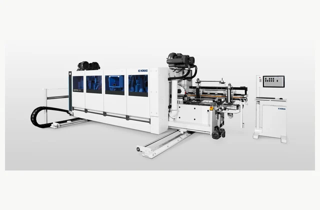
Shown as a configuration reference. Availability and the equipment offered for your project are confirmed separately.
Define the two edges and the finished joint
Provide drawings of both machined edges, the mating part and the finished component. State material construction, length or width range, thickness and surface finish. A double end tenoner processes opposed edges in a coordinated pass, but its useful configuration depends on the intended profile. Floorboard locking geometry, a square panel edge and a furniture tenon are not interchangeable tooling requirements.
Identify the reference face and the direction of travel. For flooring, explain which edges are handled in this pass and which need a separate longitudinal or transverse operation. Include coatings and decorative layers because an acceptable core profile can still leave unacceptable damage on a finished surface.
Match the spindle sequence to material removal
Review the cutting operations needed to create each edge, including trimming, profiling and any finishing units. Ask how the proposed spindle sequence divides material removal and how cutter geometry supports the required joint. A spindle count by itself does not prove that the machine can produce a proprietary locking profile, maintain its fit or machine the selected board construction cleanly.
Request a tool layout for the actual profile and identify which tooling is included. Record access rights to joint drawings and any licensing responsibility. Replacement cutters and sharpening references should preserve the profile relationship rather than be treated as generic accessories chosen after the machine arrives.
Assess chain feed, hold-down and surface protection
The board must remain referenced while opposite edges are machined. Review chain or conveyor support, hold-down arrangement, workpiece stability and the handling of short or narrow components. Uneven pressure, damaged reference surfaces or variable incoming dimensions can affect the resulting relationship between edges. Test the actual material and finish instead of judging capability only from the adjustable working width.
The HOMAG TENONTEQ D-600 reference is a flooring double-end profiling configuration. Keep that application visible when comparing it with joinery-focused equipment. Agree how the proposed infeed locates each component and how the outfeed protects freshly machined edges from impact or rubbing.
| Decision | Requirement to state | Evidence to request |
|---|---|---|
| Joint | Both edge profiles and mating geometry | Tooling layout and assembled sample |
| Material | Core, decorative face and dimensions | Trial using production boards |
| Guidance | Reference face, chain and hold-down | Stable feeding demonstration |
| Line | Pass sequence and component handling | Interface and output review |
| Changeover | Width and profile setup | Observed setup and inspected parts |
Plan profile changes and extraction around the line
Specify infeed and outfeed handling, cutter extraction, waste collection and tooling-change access. Review width adjustment and the method for verifying a new profile setup. If several machines form a flooring line, allocate reference and control responsibilities between passes. A high feed capability at one machine does not establish the production output of a line with slower loading or inspection.
Show long component travel and maintenance openings on the layout. Clarify whether tool measurement, presetting and lifting equipment are supplied. For coated panels, discuss chip removal near the finished face so a clean machining result is not compromised by loose debris in transport.
Inspect paired edges through a real assembly trial
Machine representative production material using the agreed cutters and setup. Inspect dimensions, edge relationship, squareness, profile fit, surface condition and breakout. Assemble mating parts and assess the actual joint rather than relying only on individual profile measurements. Record tooling identity and the incoming board condition, especially where core variation or decorative layers influence the finished edge.
Include a normal size or profile change if changeover is part of the purchase requirement. Examine parts from the beginning and later in the trial. Where finishing or humidity changes affect fit, agree which downstream condition will be used to judge the delivered joint.
Separate OEM labels from ODM profile development
OEM scope may include approved branding, manuals and a defined unit arrangement. ODM can involve special profiling units, hold-downs, handling or an integrated machining line. A new joint profile requires tooling review, lawful access to the design and actual assembly trials. Define ownership of tools, setup data and drawings; a reference model does not establish equivalence or authorize copying another manufacturer’s joint technology.
Keep future profiles within a reviewed machine envelope. Ask which upgrades require new spindles or a different feed arrangement rather than assuming every geometry can be added through software. Specify who supports tooling coordination when cutters, machine and joint design come from different companies.
The pictured manufacturer equipment and linked documents are technical configuration references. They do not imply authorized representation, stock availability, equivalent performance from another supplier or permission to relabel the pictured brand. Confirm the proposed equipment and commercial scope for the specific project.
What should your double end tenoner RFQ include?
- Opposed-edge drawings and mating-joint samples
- Board construction, coating and dimensional range
- Reference face, feed orientation and separate machining passes
- Required cutting sequence and included spindle units
- Profile design rights, cutter supply and sharpening references
- Chain feed, hold-down and short-component review
- Infeed, outfeed, surface protection and extraction scope
- Width/profile changeover and tool measurement requirements
- Production-board machining and assembled-joint acceptance
- OEM documentation or ODM profiling and handling integration
Need OEM / ODM customization?
Submit branding, packaging, configuration or engineering requirements for this equipment. Include the target market, initial and annual quantities, required changes and acceptance criteria.
Customization feasibility, permitted branding, development responsibilities, minimum quantity, cost and lead time are reviewed for the proposed supplier and configuration before a quotation is confirmed.
Frequently asked questions
What should I specify for a double end tenoner?
Provide drawings of both machined edges, the mating part and the finished component. State material construction, length or width range, thickness and surface finish. A double end tenoner processes opposed edges in a coordinated pass, but its useful configuration depends on the intended profile. Floorboard locking geometry, a square panel edge and a furniture tenon are not interchangeable tooling requirements.
How does a double end tenoner's tooling affect selection?
Review the cutting operations needed to create each edge, including trimming, profiling and any finishing units. Ask how the proposed spindle sequence divides material removal and how cutter geometry supports the required joint. A spindle count by itself does not prove that the machine can produce a proprietary locking profile, maintain its fit or machine the selected board construction cleanly.
Why is workpiece guidance important on a double end tenoner?
The board must remain referenced while opposite edges are machined. Review chain or conveyor support, hold-down arrangement, workpiece stability and the handling of short or narrow components. Uneven pressure, damaged reference surfaces or variable incoming dimensions can affect the resulting relationship between edges. Test the actual material and finish instead of judging capability only from the adjustable working width.
What equipment should be included with a double end tenoner?
Specify infeed and outfeed handling, cutter extraction, waste collection and tooling-change access. Review width adjustment and the method for verifying a new profile setup. If several machines form a flooring line, allocate reference and control responsibilities between passes. A high feed capability at one machine does not establish the production output of a line with slower loading or inspection.
How should double end tenoner acceptance be tested?
Machine representative production material using the agreed cutters and setup. Inspect dimensions, edge relationship, squareness, profile fit, surface condition and breakout. Assemble mating parts and assess the actual joint rather than relying only on individual profile measurements. Record tooling identity and the incoming board condition, especially where core variation or decorative layers influence the finished edge.
Can a double end tenoner be customized for OEM or ODM?
OEM scope may include approved branding, manuals and a defined unit arrangement. ODM can involve special profiling units, hold-downs, handling or an integrated machining line. A new joint profile requires tooling review, lawful access to the design and actual assembly trials. Define ownership of tools, setup data and drawings; a reference model does not establish equivalence or authorize copying another manufacturer's joint technology.
Reference information
- HOMAG: TENONTEQ D-600 flooring profiler official product reference
- HOMAG official supporting product documentation
Reference data and images explain equipment configurations. IndustryApex engineers confirm the offered model, specification and commercial scope in your project quotation.