
Choose a safety controller from a documented machine risk assessment and a defined list of safety functions. Map inputs, logic, outputs and diagnostics with qualified integration responsibility, then validate the implemented system and its controlled configuration before production use. Validate every defined function, relevant fault response, reset and power-recovery case against the approved requirements. Include final actuators and measured machine stopping behavior where applicable. Record the installed configuration and test results with responsible sign-off; a controller self-check or green indicator alone is insufficient acceptance evidence. Submit the intended configuration and any OEM/ODM changes for project-specific feasibility review.
Choose a safety controller from a documented machine risk assessment and a defined list of safety functions. Map inputs, logic, outputs and diagnostics with qualified integration responsibility, then validate the implemented system and its controlled configuration before production use.
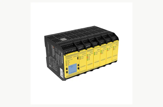
Shown as a configuration reference. Availability and the equipment offered for your project are confirmed separately.
Define each required safety function
List the hazard, triggering device, intended safe state and required response for every function. The risk assessment must establish the necessary performance and architecture. A controller's published capability is only one component input and cannot by itself establish that the complete machine achieves the required result.
Map compatible input devices
Identify emergency stops, interlocks, light curtains, scanners and other devices with their electrical behavior and diagnostics. Check supported contact or OSSD arrangements and test-pulse compatibility. Similar connectors do not make inputs interchangeable, and configuration needs to follow the exact device instructions.
Design outputs through final actuators
Include contactors, drive safety interfaces, pneumatic valves and any external-device monitoring. The stopping function continues beyond the controller terminals. Agree how the final elements reach and maintain the defined safe state and how their feedback is checked before a restart is permitted.
Separate status communications from safety
Specify the host network and the information needed for troubleshooting. Ordinary Ethernet or fieldbus status data should not be treated as safety communication without the appropriate supported implementation and validation. Diagnostic convenience cannot replace the engineered input, logic and output path for the safety function.
Control reset and operating modes
Define manual reset, start/restart, mode selection and any muting or bypass functions with the risk assessment. Explain where the operator stands and what can be observed. A reset command must not be casually equated with permission for hazardous motion, especially after access or a power interruption.
Keep a validated configuration record
Obtain project files, software version, controller identifiers and a controlled approval record. Changes to logic or connected devices require the relevant reassessment and tests. A printed logic diagram without the actual downloaded configuration and validation evidence is an incomplete service and handover package.
Compare a complete safety controller scope
| Decision | Information to compare |
|---|---|
| Define each required safety function | Risk assessment, safety-function list, safe states and required performance |
| Map compatible input devices | Input models, contact/OSSD types, test pulses and diagnostic requirements |
| Design outputs through final actuators | Final switching elements, feedback monitoring, stop response and restart permission |
| Separate status communications from safety | Host network, status data, supported safety communications and system boundary |
| Control reset and operating modes | Reset location, modes, muting/bypass scope and restart interlocks |
| Keep a validated configuration record | Configuration files, software/version, identifiers, access controls and validation record |
Plan installation and access
Qualified personnel should follow the documented cabinet, wiring, power and grounding design for all safety components. Provide segregation and environmental protection as specified. Commission within an approved test plan that controls access and prevents testing from exposing people to the hazards being evaluated.
Agree acceptance evidence before ordering
Validate every defined function, relevant fault response, reset and power-recovery case against the approved requirements. Include final actuators and measured machine stopping behavior where applicable. Record the installed configuration and test results with responsible sign-off; a controller self-check or green indicator alone is insufficient acceptance evidence.
Define OEM/ODM engineering boundaries
OEM cabinet layout and approved integration may be reviewed. ODM safety logic, electronics or functional changes require qualified engineering, risk reassessment and renewed validation. A reference controller image does not certify an IndustryApex machine, imply stock or authorize reproduction of the manufacturer's system.
What should your safety controller RFQ include?
- Risk assessment, safety-function list, safe states and required performance
- Input models, contact/OSSD types, test pulses and diagnostic requirements
- Final switching elements, feedback monitoring, stop response and restart permission
- Host network, status data, supported safety communications and system boundary
- Reset location, modes, muting/bypass scope and restart interlocks
- Configuration files, software/version, identifiers, access controls and validation record
- Destination, working environment, access and delivery constraints
- Installation responsibility, utilities and connection drawings
- Acceptance samples, documented test method, operator training and maintenance scope
- OEM/ODM changes requested: identification, tooling, interfaces or new design; engineering feasibility to be confirmed
Need OEM / ODM customization?
Submit branding, packaging, configuration or engineering requirements for this equipment. Include the target market, initial and annual quantities, required changes and acceptance criteria.
Customization feasibility, permitted branding, development responsibilities, minimum quantity, cost and lead time are reviewed for the proposed supplier and configuration before a quotation is confirmed.
Frequently asked questions
How do I define each required safety function?
List the hazard, triggering device, intended safe state and required response for every function. The risk assessment must establish the necessary performance and architecture. A controller's published capability is only one component input and cannot by itself establish that the complete machine achieves the required result.
How do I map compatible input devices?
Identify emergency stops, interlocks, light curtains, scanners and other devices with their electrical behavior and diagnostics. Check supported contact or OSSD arrangements and test-pulse compatibility. Similar connectors do not make inputs interchangeable, and configuration needs to follow the exact device instructions.
How do I design outputs through final actuators?
Include contactors, drive safety interfaces, pneumatic valves and any external-device monitoring. The stopping function continues beyond the controller terminals. Agree how the final elements reach and maintain the defined safe state and how their feedback is checked before a restart is permitted.
How do I separate status communications from safety?
Specify the host network and the information needed for troubleshooting. Ordinary Ethernet or fieldbus status data should not be treated as safety communication without the appropriate supported implementation and validation. Diagnostic convenience cannot replace the engineered input, logic and output path for the safety function.
How do I control reset and operating modes?
Define manual reset, start/restart, mode selection and any muting or bypass functions with the risk assessment. Explain where the operator stands and what can be observed. A reset command must not be casually equated with permission for hazardous motion, especially after access or a power interruption.
How do I keep a validated configuration record?
Obtain project files, software version, controller identifiers and a controlled approval record. Changes to logic or connected devices require the relevant reassessment and tests. A printed logic diagram without the actual downloaded configuration and validation evidence is an incomplete service and handover package.
Reference information
- Banner Engineering XS26 official product reference
- Banner Engineering safety controller official family or technical reference
Reference data and images explain equipment configurations. IndustryApex engineers confirm the offered model, specification and commercial scope in your project quotation.